No good thermal path yet - but I don’t believe the cause was bad heat dissipation, since the LEDs died after a few seconds already. I haven’t opened the head yet but as far as I can see the bond wires are blown.
Interesting. In either case the MCPCB would get pretty darn hot. Pumping 70W thermal into a 10g Al MCPCB would cause the temperature to rise ~8 degrees C/sec.
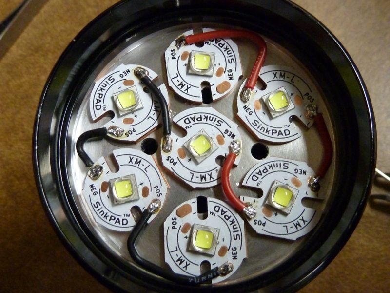
New LEDs arrived, reflowed 7 genuine XM-L2. Very bright, none of the LEDs popped up to now, but it’s pulling only 24 Amperes out of brand new Samsung 30Q button top. FET+1, thick/double wires, all springs bypassed - shouldn’t it be more Amps? I wonder if the cells are genuine.
???that sounds like a inappropriate plug of your new flashlight??? That light has nothing in common with that cheap AA zoomie in the picture, it is even not a zoomie.
Ahh, are you using the stock cheap MCPCB? Yikes! Living dangerously with good XM-L2's. There's some significant points of loss's in these cheap SRK clones. Many we can fix, but I suspect some not so easy, I've been finding. I beef up the traces, or reduce/eliminate them on the tail PCB, then there's the bridge from the batt+ contact to the LED side of the driver -- not sure that's good. In single cell lights, you can run heavy gauge wire from the driver spring bypass direct thru the driver board, but not so easy in a SRK. Then there's that stock MCPCB - oh boy... I'm also not confident with the the connection of the tail PCB to the housing - actual conductive contact could be suspect, cheap screws - no brass or copper there, maybe limited contact surface.
Could be one of these things, or a combo of small loss's over them all. Doubt it's the cells.
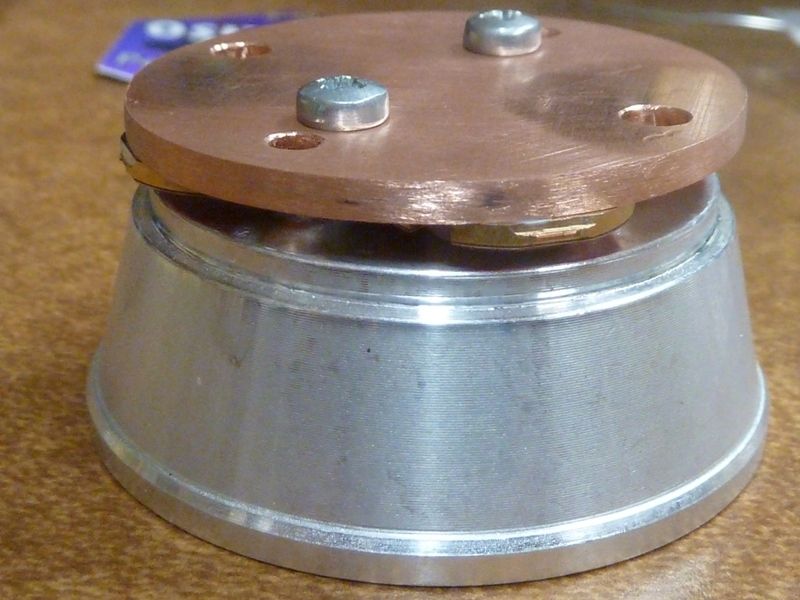
Yes, I’m using the stock MCPCB, but it’s not that bad, rather thick. Even no copper plate below (too careless, I know), don’t have any yet, but the housing gets very hot quickly, so heat dissipation should not be that bad either. I did most of the things you proposed, even managed to lead batt+ through the driver board with a very fat cable (1 more ampere). Haven’t done this with batt- yet, but here are more stock lead throughs. What’s still missing is a better connection of tail PCB to the housing, should have removed the anodization there. Will do it when I have to repair the spring bypasses one day, I don’t want to open it too often since one of the screw threads in the housing is already damaged.
I’m using the cheap XM-L2 U2 3D from fasttech, the warm tint is very nice, althought I’m not sure if all LEDs really have the same bin. Replaced the stock lens with a coated one. I’m using my own firmware with optional stepless ramping.
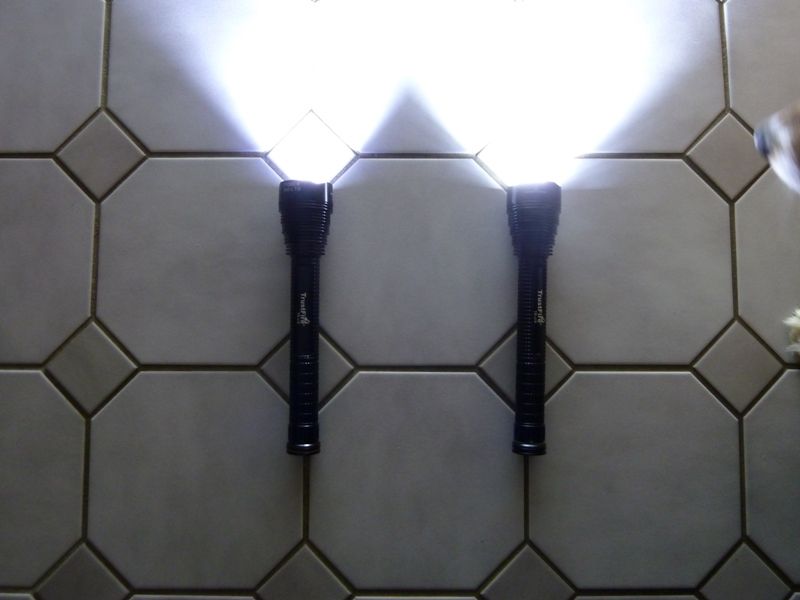
Anyway, I fell in love with this light, with 30Q it delivers about 6500 lumens at start, with older Keeppower protected still 5500 lumens. Not bad for a 20$ light and 30$ modding parts.
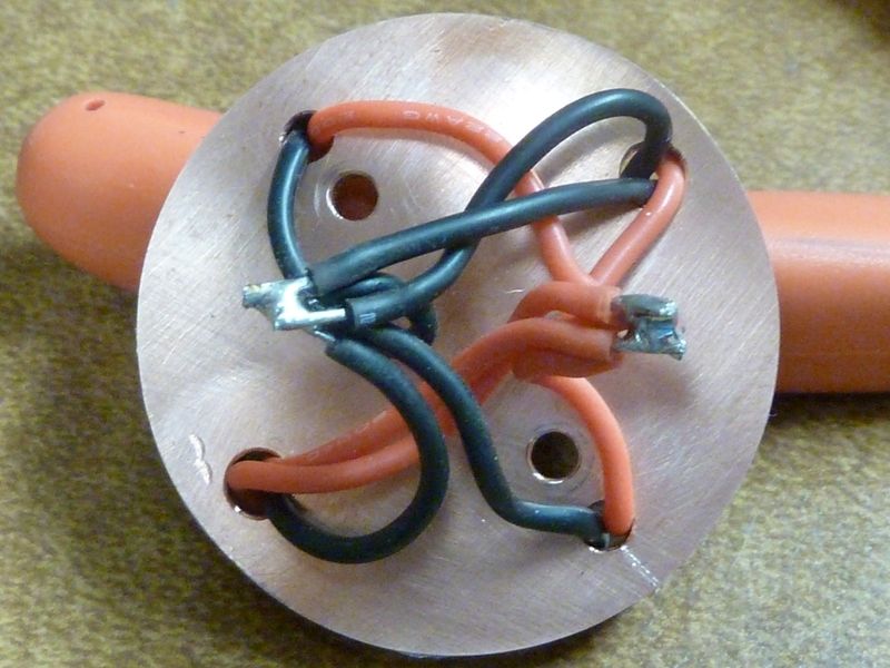
Btw., thanks for your idea of doing a wire loop at the tail PCB in order to measure current with a clamp meter easily.
A one-piece 45mm copper core quad DTP PCB can be made for under 10 dollar each, minimum amount 100 pieces. I don’t know yet what board the Q8 will come with, but once 500+ Q8’s are around it may be feasable to have an extra board made for it.
THe 7xSRK is quite common (and looks nicely symmetrical ) so that may be a candidate too for a custom board, I expect that if someone goes for having one made, he/she will sell out. But 800 or so dollar is a risky investment for a hobby of course.
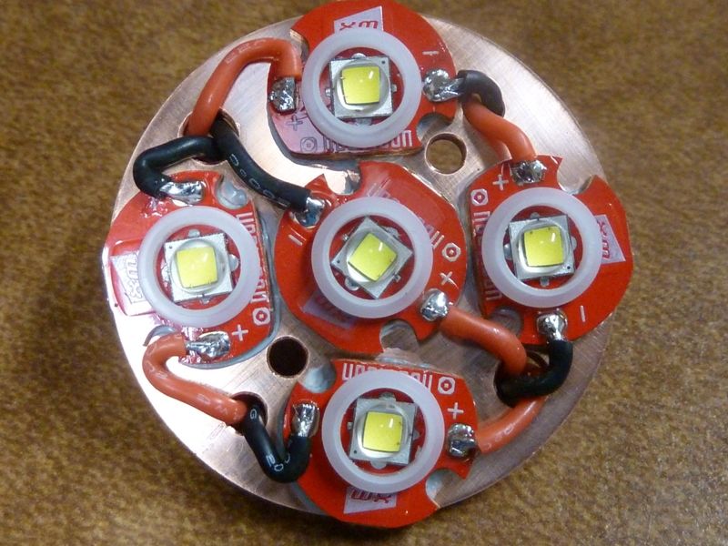
I've done a couple of 7X lights, the J18, not an SRK yet (I have a 7X SRK still to do). I was able to use 16mm copper boards. I go with the biggest you can fit. We can get 14mm TPAD's now if 16's don't make it. It's good to hear you are getting the heat out, but definite amps and output loss's from the non DTP alum MCPCB - going thru thin traces rather than copper wires has to have loss's.
I also did a 5X SRK with 16mm copper MCPCB's - no problem at all, but with some trimmed. MY 5X SRK does over 6,000 lumens using XM-L2 U3 3D's I believe.
Nice pictures!
I’m confident if I’m going to glue 7 LED boards to the heat sink at least 3 of the LEDs will be smudged afterwards. But perhaps I’ll give it a try. New SRK is on the way …
I’m prettty sure the LEDs won’t hit their expected life time of 50,000 hours. Let’s see if they survive the weekend …