Hello all,
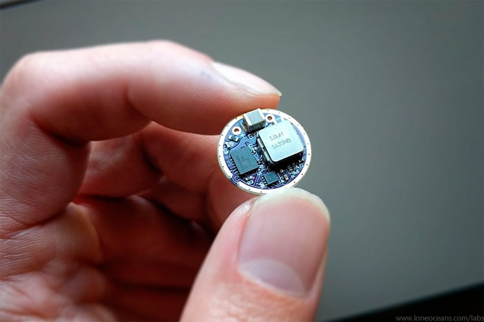
I finally managed to grab some time and spent last weekend reworking my GXB20 driver to a 17mm form factor, which was by far the most popular request. Introducing the 17mm GXB17 6V 3A boost driver!  For those unfamiliar with my GXB20 driver, please take a look here: https://budgetlightforum.com/t/-/44107
Update (2018!)
The GBX17 has been superceded with the newer GXB172 which handles 2.5x more power! As a result I will discontinue development on the GXB17. See this page for more details on the GXB172! https://budgetlightforum.com/t/-/50015
Drivers for Sale?
I've been getting a few messages if these drivers are for sale, so I thought I'd just answer them here! Thanks for you interest, but unless stated otherwise. I have none for sale yet. In fact the PCBs have just been sent for fabrication (as of 10th June) and I still need to assemble and test them. The PCBs will take at least 1-2 weeks before I even get my hands on them. In addition, even after development I will not be able to offer any assembled drivers for sale, unless I get some help in getting them semi-mass produced at the factory. Finally, note that I really wasn't intending this to be a commercial driver - it was always meant to be a hobby, just for fun project for my own flashlight! However if you are interested please feel free to follow this thread and I will provide updates whenever possible!
TL;DR:
The GXB17 is a smaller form factor of the GXB20 driver I made for fun not to long ago. The GXB17 (as is the GXB20) is a simple constant-current single-cell (e.g. one 18650) programmable boost LED driver, designed specifically to be powered by a single lithium cell. It is designed to drive 6V 3A LEDs like the XHP50 and Nichia 144 LEDs, but can also be configured to run in 9V and 12V output, with a nominal maximum power of around 18+W and higher in boost for shorter durations.
The GXB17 incorporates all the features of the GXB20, but as its name implies, is a 17mm diameter driver.
The GXB17 is a true constant current driver which takes drive current feedback and regulates the output voltage to match the desired current. The driver is fully programmable with an on-board ATtiny84A and includes features such as temp-sensing, battery voltage sensing, off-time memory, and runs at >90% efficiency at most output levels. It also has pins for an optional e-switch if desired.
Finally, the GXB17 was designed as a fun hobby project, and definitely not designed to be a commercial driver in mind - i.e. no optimization was made for cost, component count or ease of fabrication! That said, it's a fairly full featured driver and I hope it will be something all hobbyists here can enjoy!
Current Status:
GXB17 v1 PCBs have arrived and I have got one soldered up. Testing in progress..
Feature List:
- Input - 1S (e.g. single 18650), ~2.6V to ~4.3+V
- Output - 6V 3A or 12V 1.5A nominal
- True Constant Current control, 256 levels
- 17mm Diameter
- Attiny84A Programmable
- Off-time capacitor with EEPROM memory
- Temperature Sensing
- Battery Voltage Sensing
- Extra GPIO for Mode or E-Switch with your desired firmware
- Efficiency >90%+ for most output levels
- 2 Layer PCB
Design and Operation
Designing the GXB17 was a little bit more work, mostly because of its much smaller size than the GXB20. It only has 72% of the PCB space as the GXB20, or 60% the footprint of competing 22mm drivers! In addition, I wanted to design it to fit OSHpark PCB fab requirements, and not go to a 4 layer board. Furthermore, I wanted to incorporate all the features of the GXB20 with no compromises in power output or features. I know the design can be significantly optimized for less parts etc, but I liked the configurability aspect of the GXB20, so I simply ported over the entire schematic and did a new layout for the GXB17 with only a few component optimizations.
The result is the exact same functionality of the working GXB20 but in a smaller form factor, with the following features:
- (1) proper constant current operation and brightness modes
- (2) programmability
- (3) safety features (over-temperature cut-off etc)
(copied from my GXB20 post:) For adjusting brightness, a simple and commonly done way is to have a fixed boost voltage, run the LED across a current limiting resistor, and then use a FET and PWM to control LED brightness. This works OK, but due to the V_fwd inconsistencies of LEDs, this can lead to widely differing LED brightness. In addition, PWM generates flashing/strobe effects, which is not as pleasant as a true constant-current limiting circuit. In the GXB17/20, the LED I_fwd current is constantly sampled across a small current-sense resistor. This value is then amplified via a digitally variable amplifier (controlled via an Attiny84A) and fed into the boost power circuit. The boost circuit then regulates the voltage to maintain the desired current.
For programmability, I decided to go for an Atmel ATtiny84A instead of an Attiny85 due to the fact that it came in a very small 3x3mm QFN package, has EEPROM for storage of memory modes, allows me to use the hobbyist-friendly Arduino environment for sharing / open-source, and comes with a lot more GPIO for additional features. The next revision will probably use a newer ATtiny841.
Other features includes things like battery sensing (so I can turn off the LED drive if the battery voltage falls too low), as well as real-time temperature sensing for dynamic LED brightness control if it gets too hot. Extra GPIO(s) is also available for e-switch and/or mode operation with modifications to the firmware!
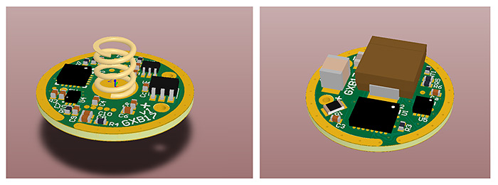
Here's a render of how the board layout looks like. Care was taken to optimize power and logic traces so they interfere as little as possible, yet still fit completely on a 17mm 2-layer PCB - and I tried to use no smaller than 0402 components for almost the entire design. Certainly going 0201 and using 4 layers would be even more optimal, as would be using stricter PCB rules such as 4/4mil or 3/3mil! But then I wouldn't be able to order them on OSHpark or cheaper fab houses.
p.s. It looks like the outside ground ring is not 'closed' but it is in fact closed. Just that there is a little gap due to the soldermask - I had to add the soldermask since I could not avoid a small trace running right along the periphery of the board.
Since the design is basically the same as the GXB20, the same firmware can also be used on the GXB17.
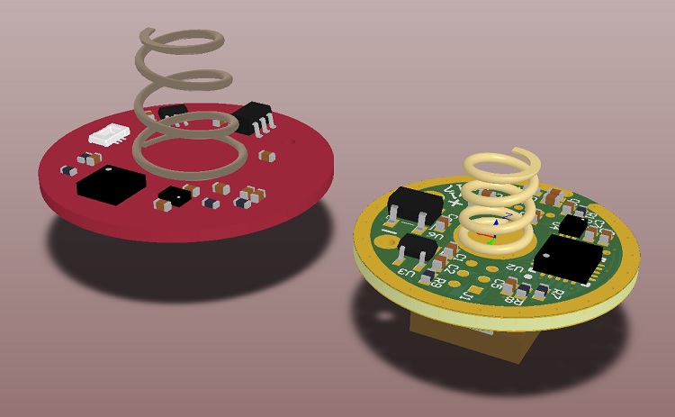
Above shows a quick preliminary to-scale comparison between the GXB20v2 and the GXB17v1 driver.
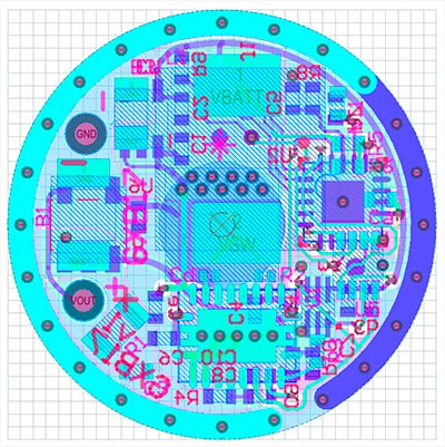
Above is the layout of the driver; a little hard to see but the board space is fairly well used up, though I think I could probably optimize it even more with a little more work! Programming is done via a 50mil 6-pin pad array where a 6-pin header can be used via contact-programming. I decided not to go for the molex micro-stack header since I had a poor experience using it in the GXB20 where it would often get stuck and come out.
Right now I've ordered a few preliminary PCBs to assemble and verify the design.
Note that again this driver was designed as a 'for fun' driver, mostly because I wanted a small flashlight driving a big LED. I never expected such a good response from it, nor did I design this for commercial manufacturing (where I would have optimized component choice, cost, component count etc), but I'm looking forward to seeing where this will go.
Hopefully this will be a driver which people will find useful. 
Thanks for reading and I'll continue to post updates as this project progresses.