Just a small update today.
Lots of thought has been going on in my Moose mind which probably explains a lot, on how to incorporate the fan and drill lots of cooling holes without interfering with wiring and mounting holes for the different components.
I think I’m nearly there so just going to carry on.
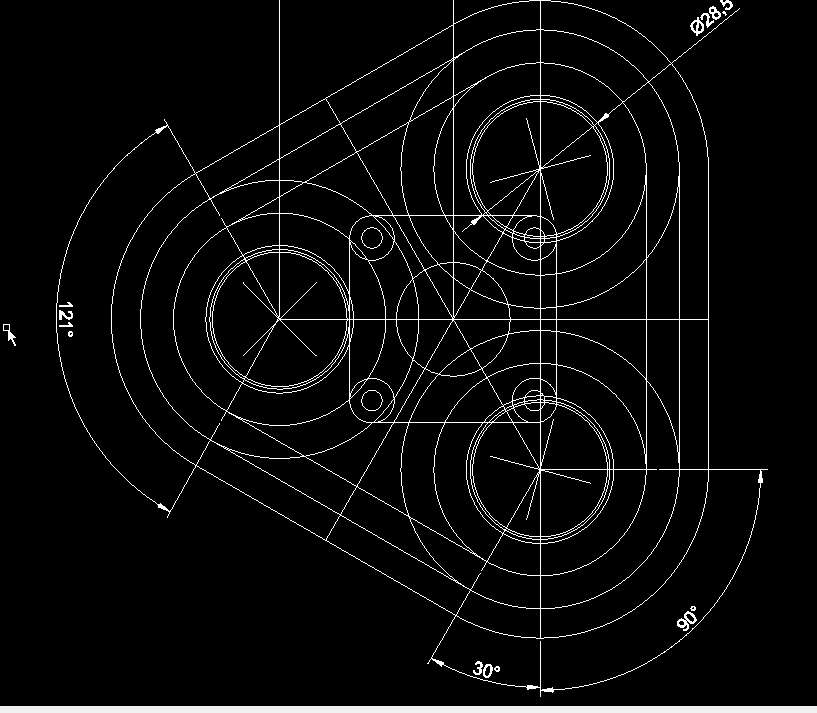
This has been redrawn a dozen times and hopefully with a few more holes in it I can start machining. This part will have the reflectors threaded into in and also locate the MCPCB’s which will be screwed down into the next section which will house the fan.
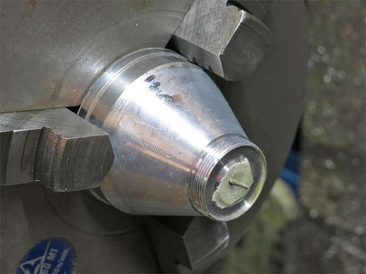
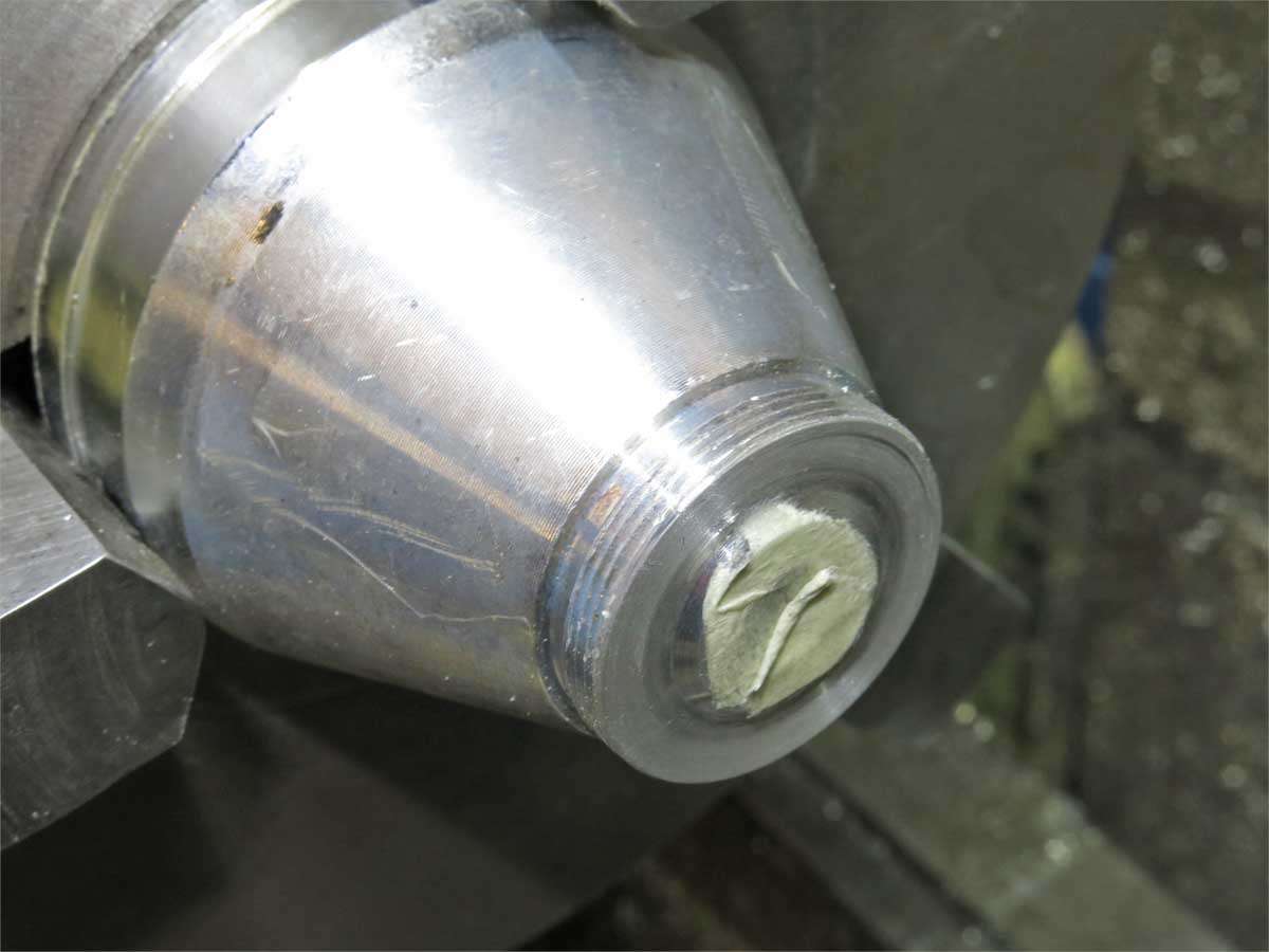
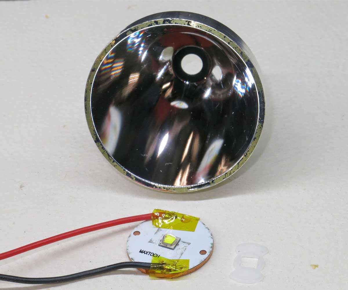
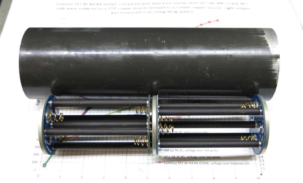
The test reflector was placed into the three jaw chuck to machine the ends of the threads off flush with the base to give clearance for the wiring.
To tune the reflector to the led different width isolators were used.
This was an interesting exercise tuning the reflector as by shining the light on the door of the shed the further into the reflector the led was the smaller brighter the hot spot appeared.
On getting the light meter out to test what I saw with my eyes a different story emerged. The highest reading on the light meter at about 4 meters was with between .6mm to .8mm isolator. This gave a larger hot spot and a fair amount of spill compared with having the reflector base sitting on the base which gave a clearly defined tiny hot spot.
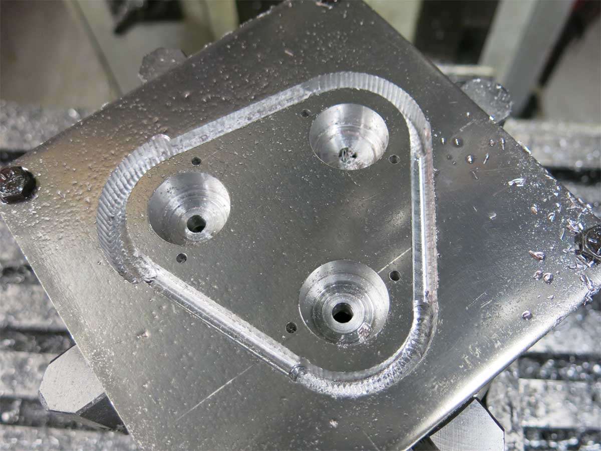
I’ll save the boredom of showing another triangle with a squillion cuts on this final triangle piece. The three larger holes will be threaded for the reflectors. Yes it was a whoops in one corner but probably turned out for the better as the triangle is a few mm smaller than it would of been if it was machined to the size I drew it up as.
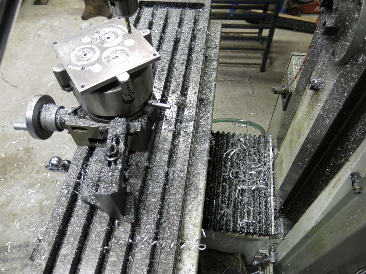
As the lathe and mill had not been cleaned down for a few weeks that was the first job on the agenda after the above piece was finished. This picture doesn’t do the mess justice.
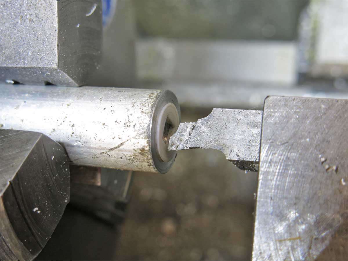
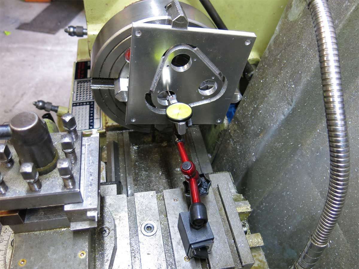
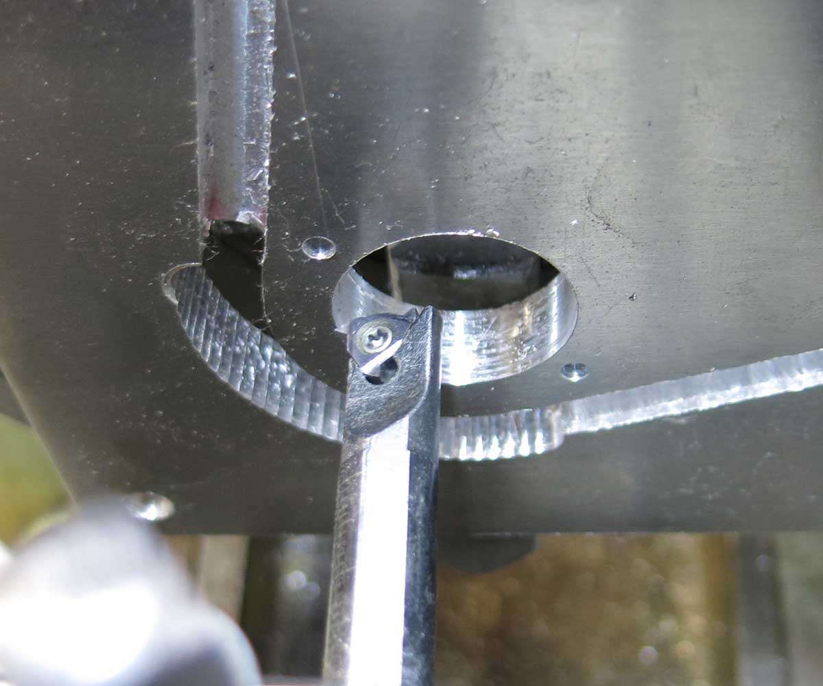
Back to the lathe and the piece was set up in the independent four jaw chuck for threading.
One thread later and will the reflector screw in?
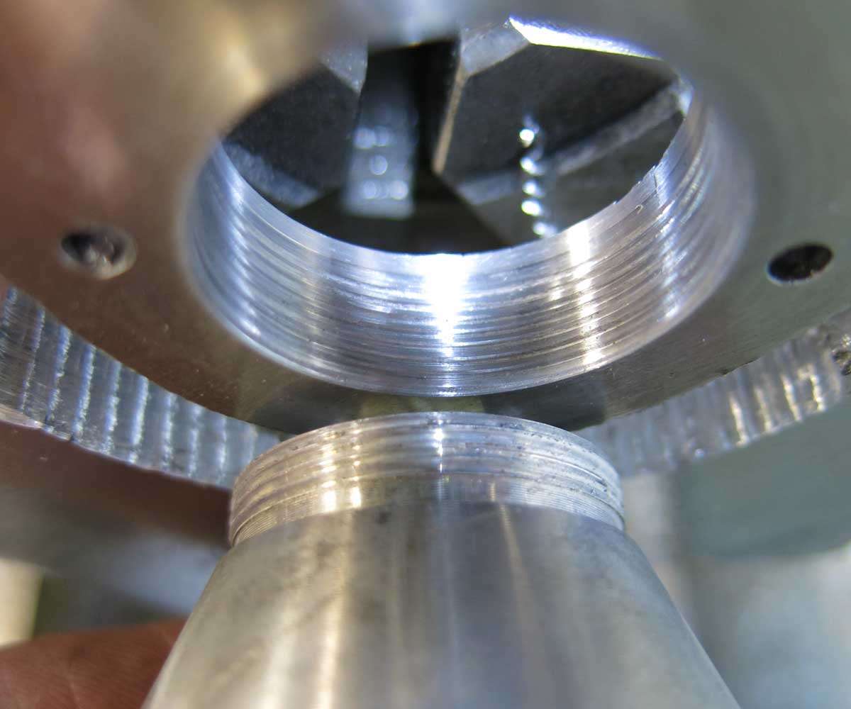
Yes it does screw in. One down two to go. Its odd that even after screw cutting hundreds of threads I still get nervous that something will go wrong.
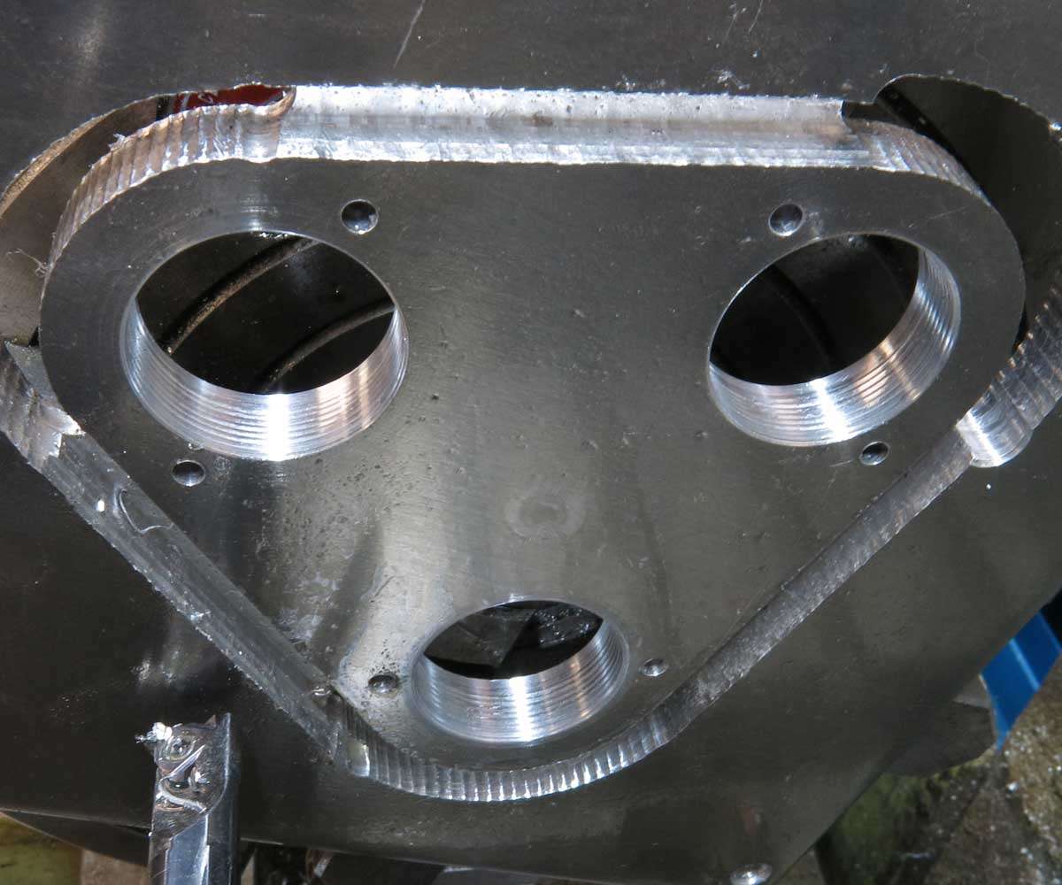
And finally we have three threads ready for reflectors.
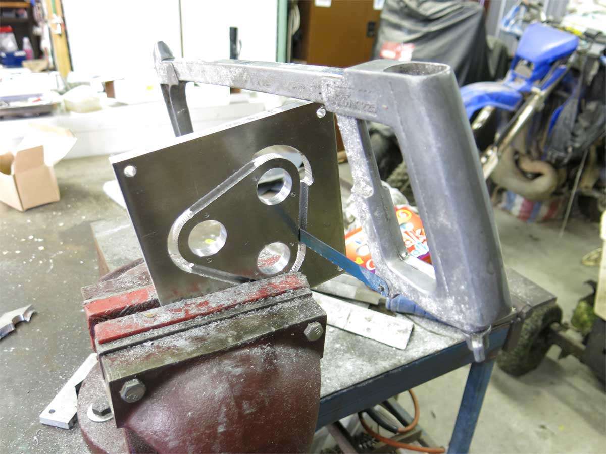
And then the so called magic hacksaw was ordered to do its bit. Yeah sure.
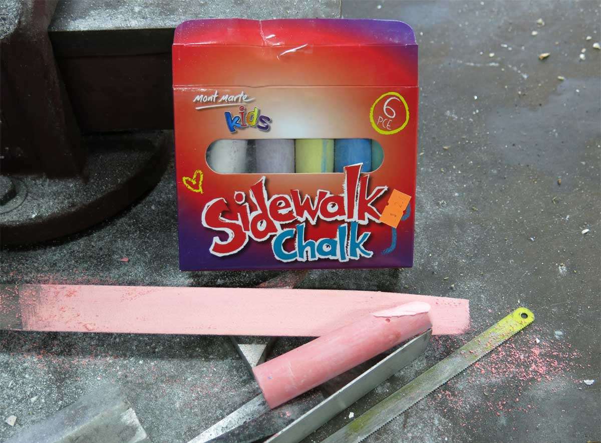
I asked SHMBO to get me some chalk when she went shopping next as I’d run out of white chalk. She came back with this saying it would make a difference. Well being the doubtful type I was surprised that it did make a difference. The coloured chalk made a pretty big difference. :person_facepalming:
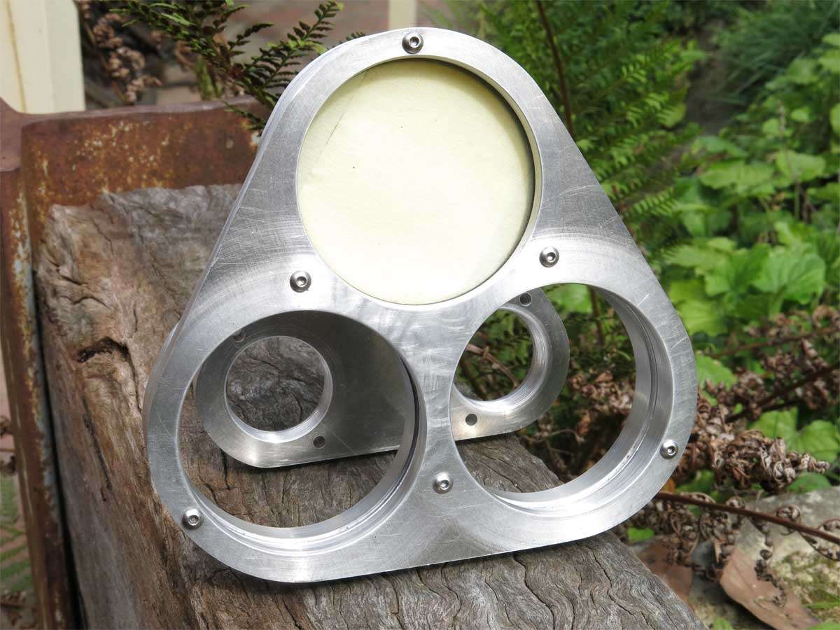
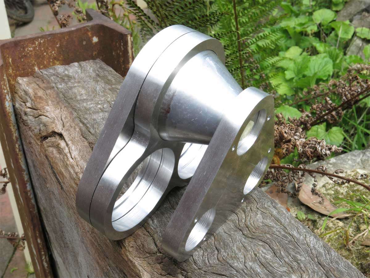
After lots more filing we had this. It assembled with one reflector ok. Will it assemble with three? Who knows.
To me it looks like I made a top and bottom triple clamp.
I’m now back to the drawing board on how to proceed next. The item will house the fan, have cooling holes and the top face will have the leds mounted to it. I hope. :question:
Well, the hacksaw must be magic - passing through a solid object like that…
That’s starting to take shape now, & really wouldn’t look out of place on a custom bike.
When I haven’t been posting about Drag Week, I’ve spent today making moulds for my build, & keeping an eye on Jack & his buddy who’s come around to check out the build…
This weeks update is more about failures than moving ahead.
Trying to hasten the speed of the build up a bit I spent an hour or so in the evenings after work each night in the shed.
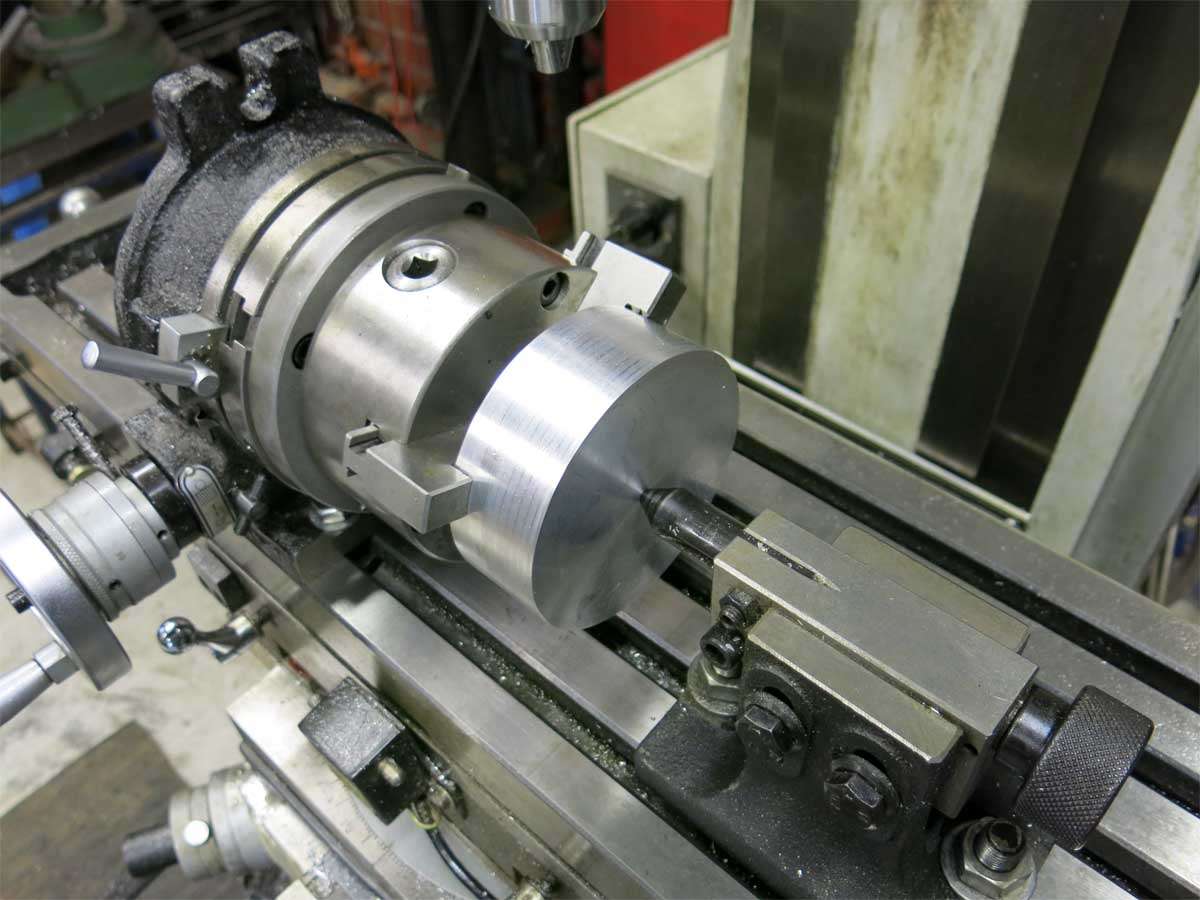
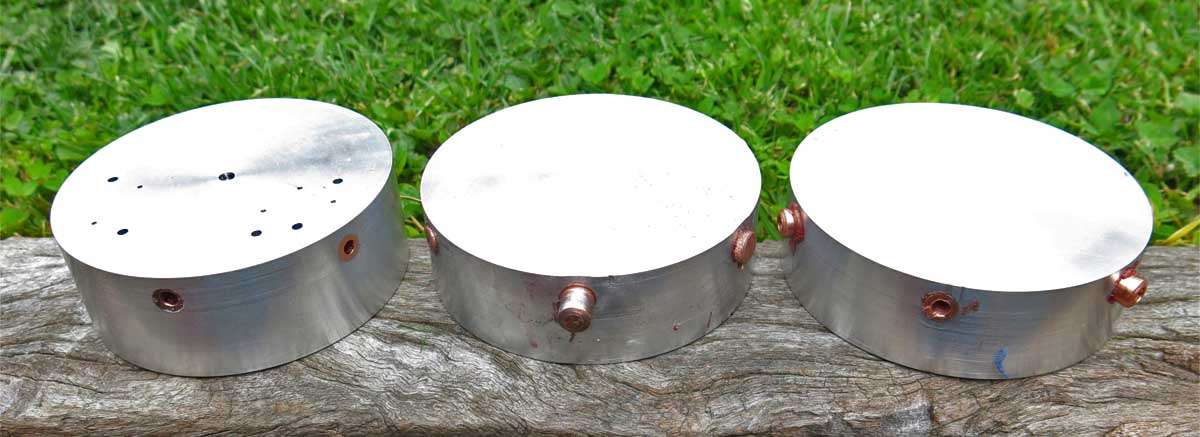
Work started on the part that will house the fan on one side and the leds on the other.
The aluminium here is about 110mm in diameter and 44.5mm in width.
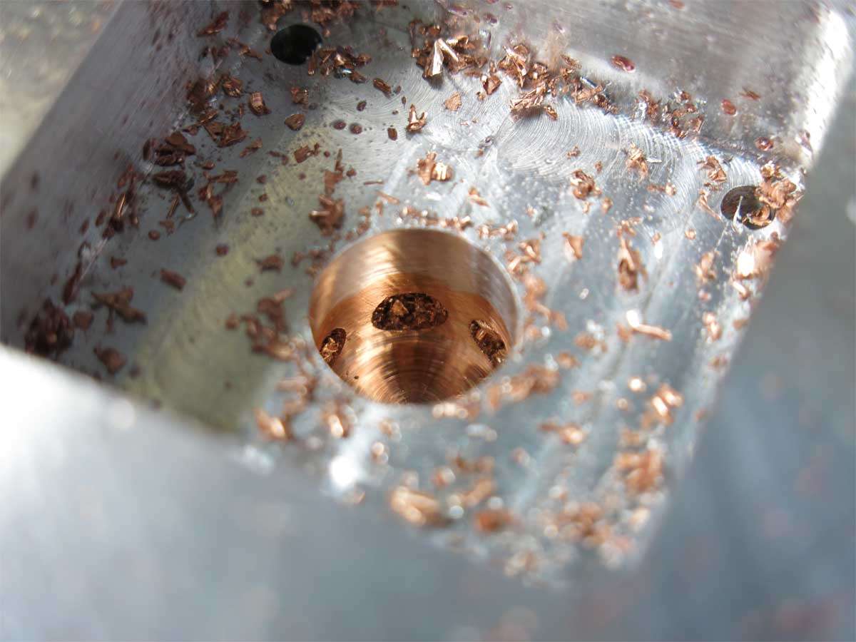
3 x 3/8’’ holes were drilled spaced at 60 degrees.
This allowed 3/8’’ copper bar to be inserted through the aluminium.
Long story short, I drilled two of the 1/8’’ through holes in the wrong spot. Wrong PCD.
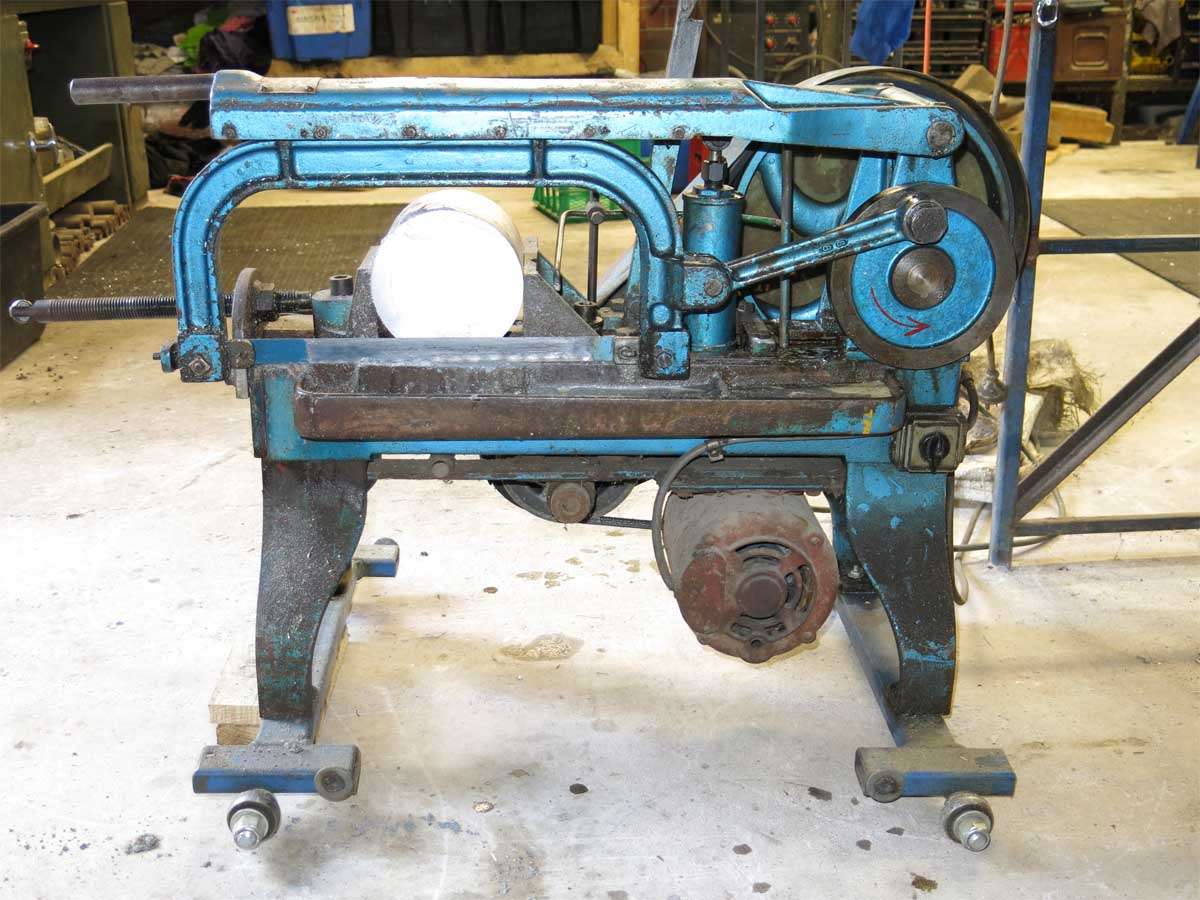
Starting again I only had 150mm diameter aluminium bar so this was cut to length in the older than I power hacksaw.
On knocking the copper rod through the holes on the second one, the copper picked up internally and butchered the aluminium.
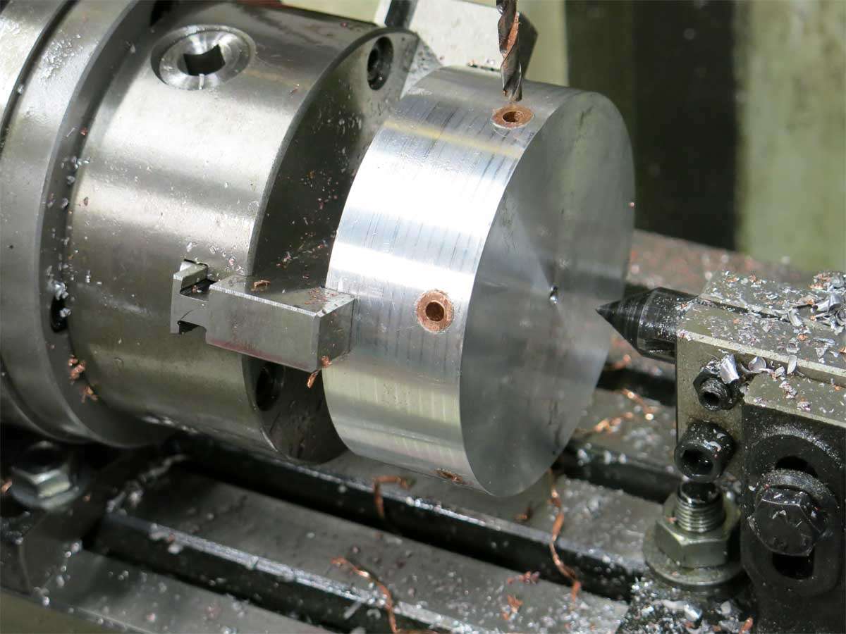
The third one I managed to get the copper through ok.
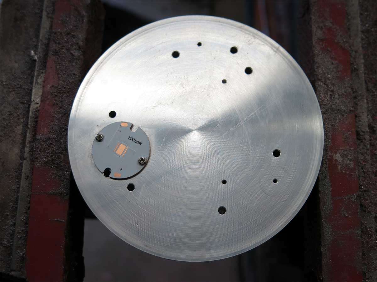
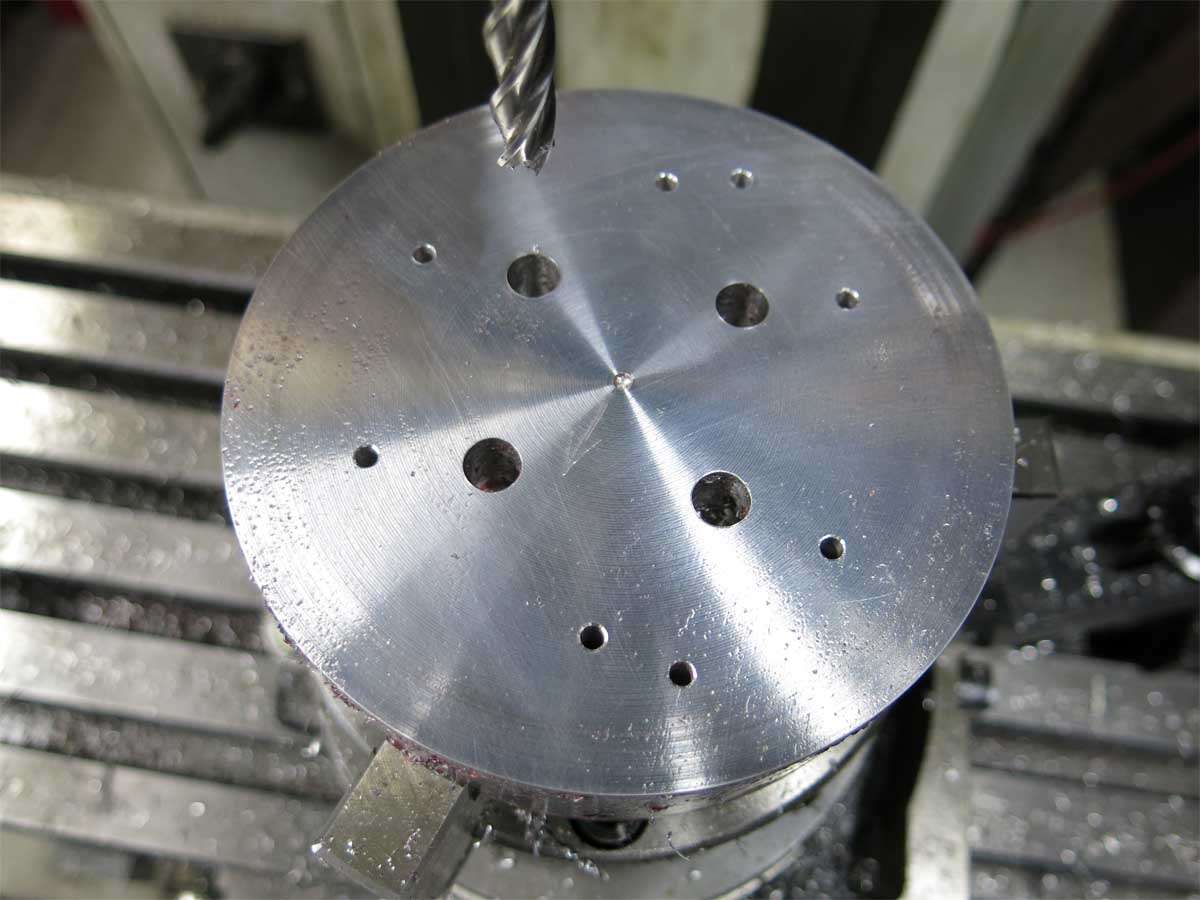
Lots of holes were drilled and the MCPCB bolt holes were tapped M2 and yes I snapped a tap of in one of the holes. I really will have to get the correct drill for this size tap. Luckily for me it wont matter as the MCPCB’s will also be held down with the reflectors.
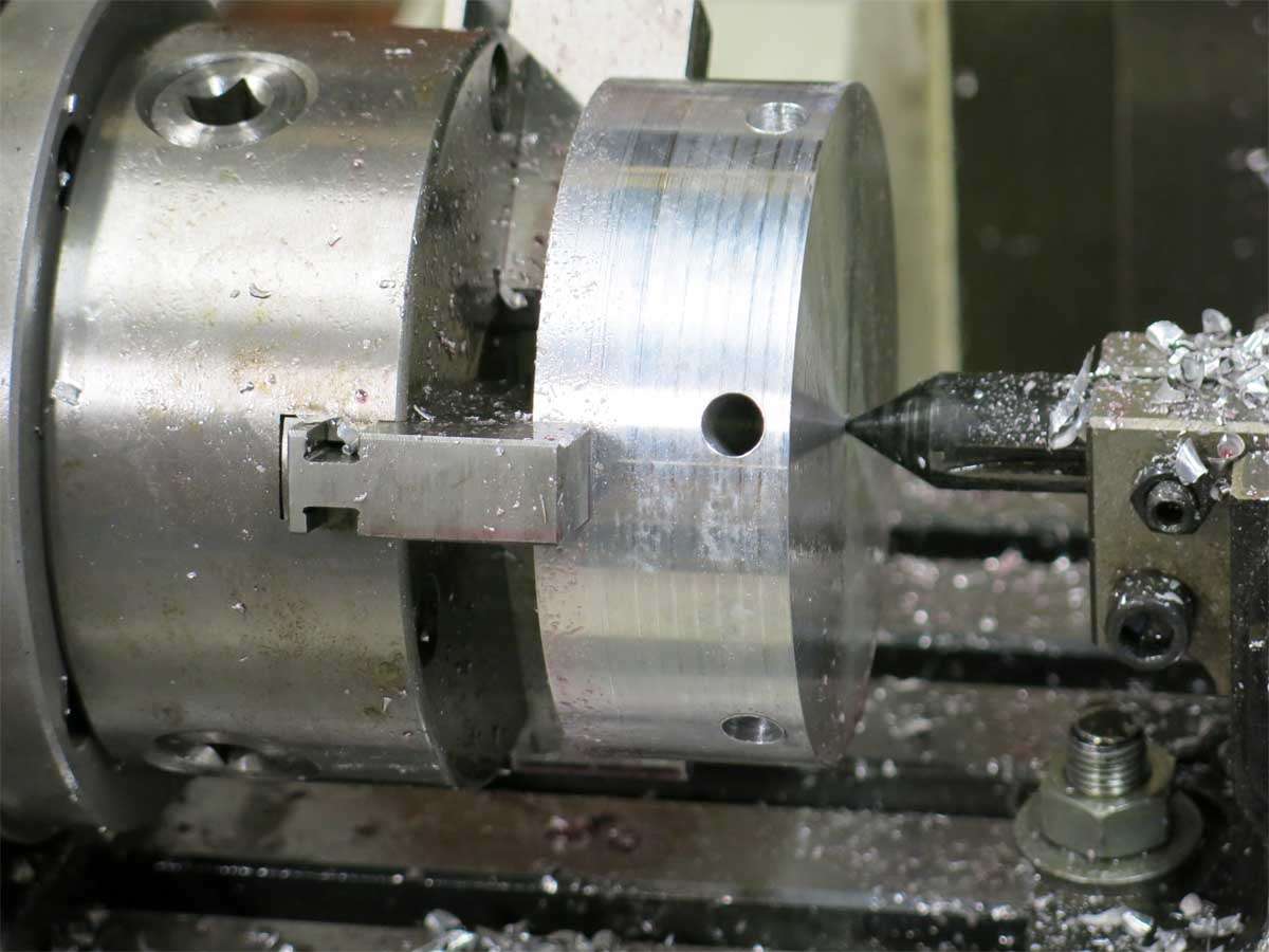
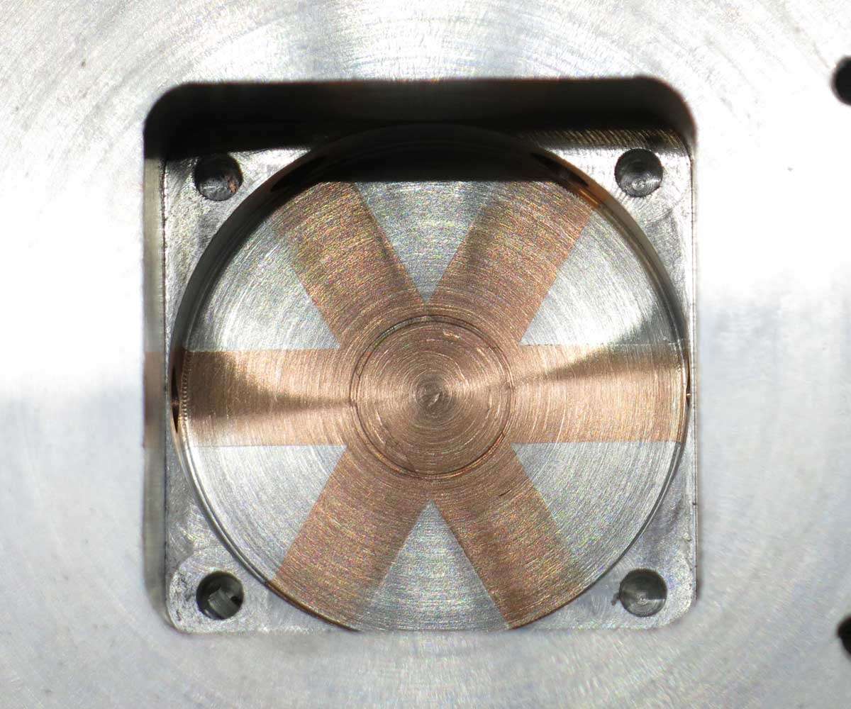
Six 1/8’’ holes are through holes that will let the cap screws pass through from the reflector part with the reflector threads in it, through this section end up screwing into the next section which will hold the driver.
The two random holes are to allow the power wires to feed through to power the leds.
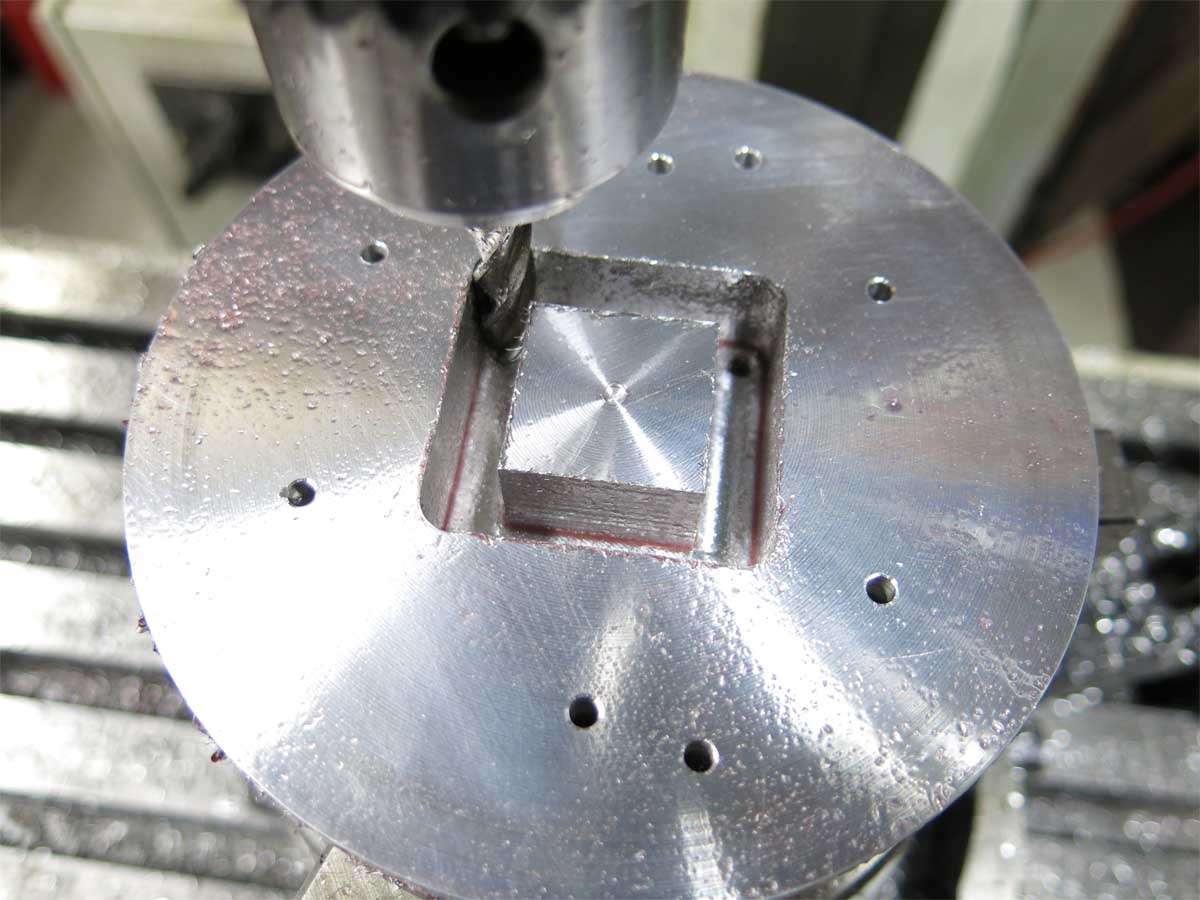
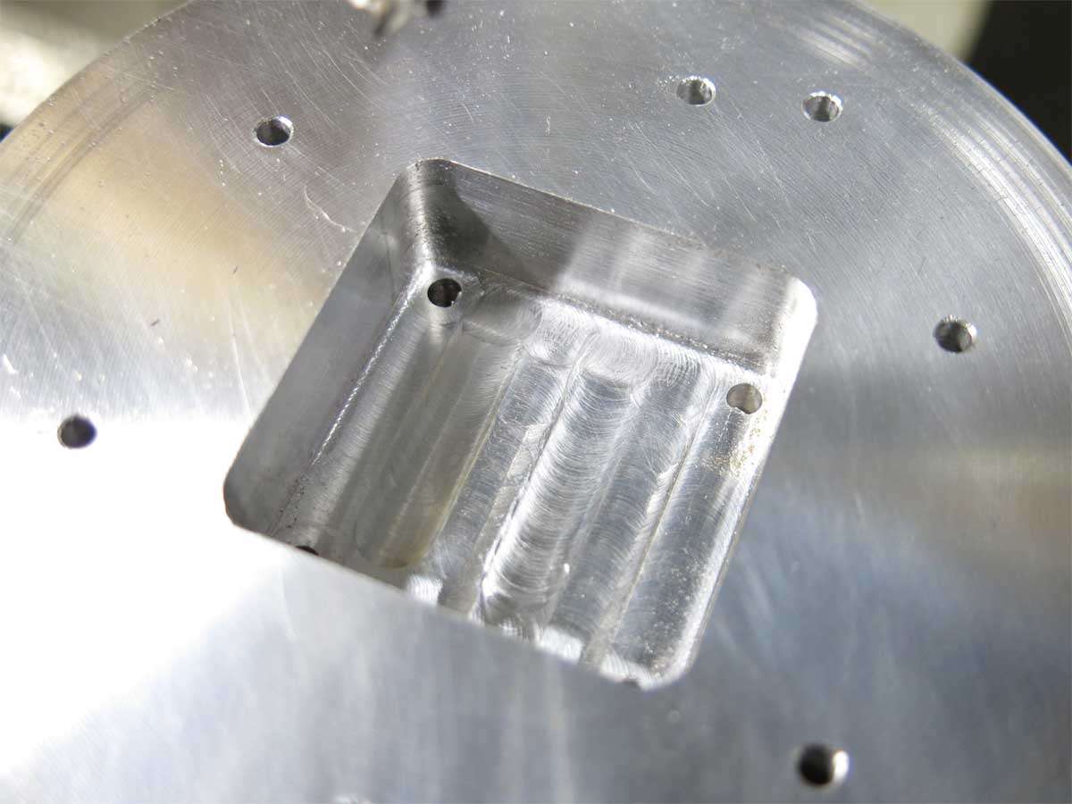
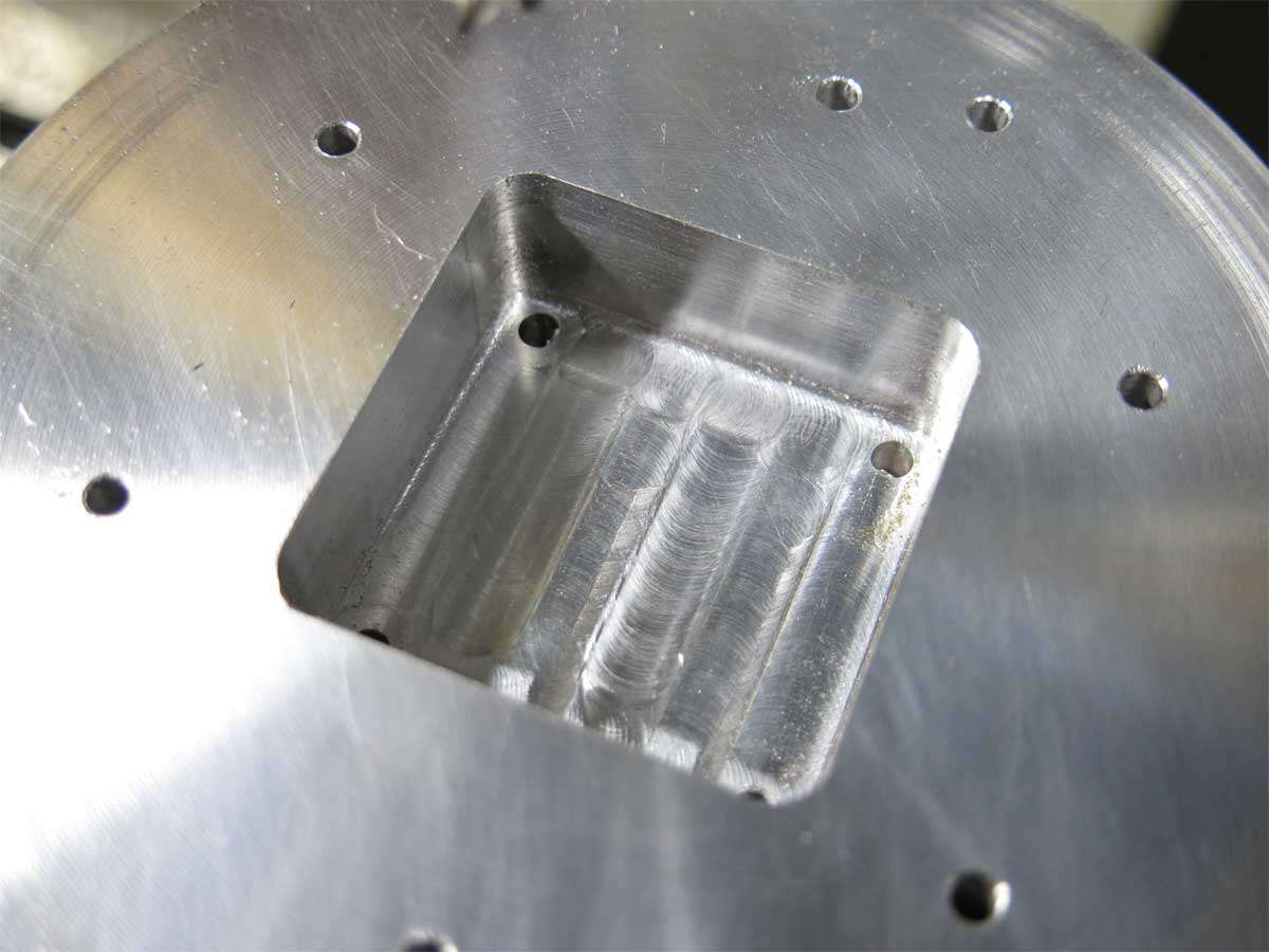
The four large holes here are for the fan cavity.
And a moat appeared.
The through holes for the cooling are yet to be machined.
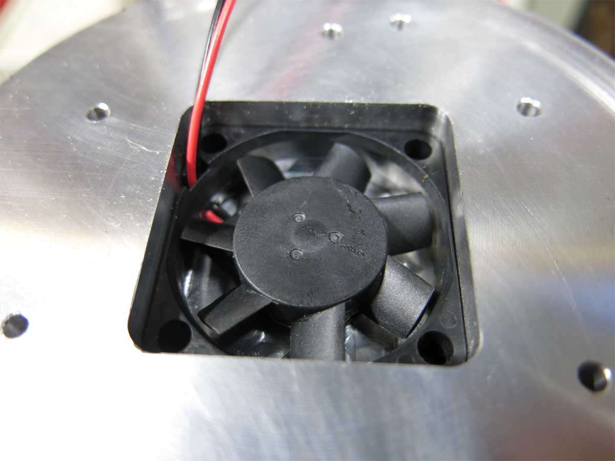
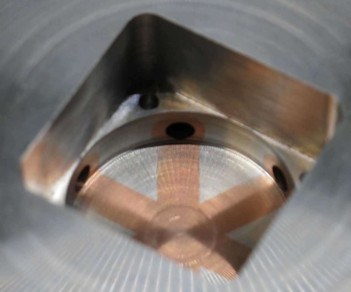
And finally the fan in its new home, temporarily at least.
On testing the fan it was found the more gap on the inlet side between the fan itself and obstruction above it the more air it moved. On this basis the hole recess was deepened further.
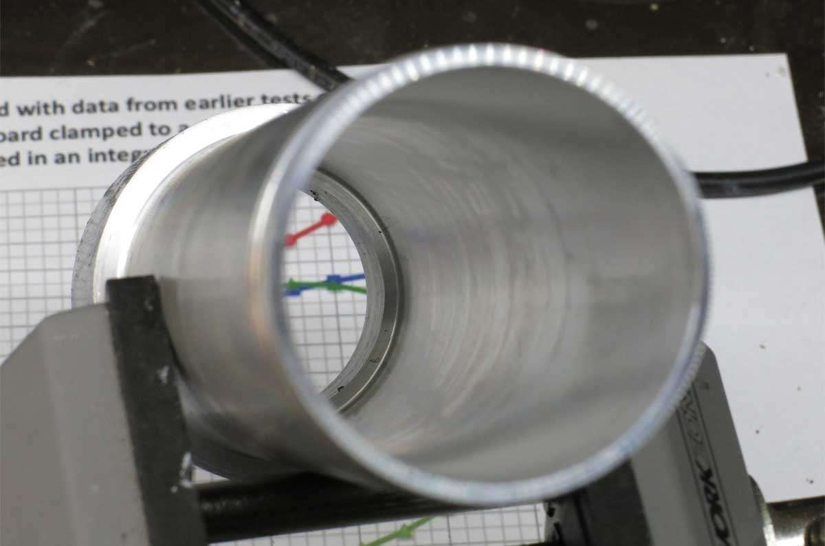
A hole was then milled out to 19mm in diamter through the copper heat tubes.
This was then machined out in the lathe.
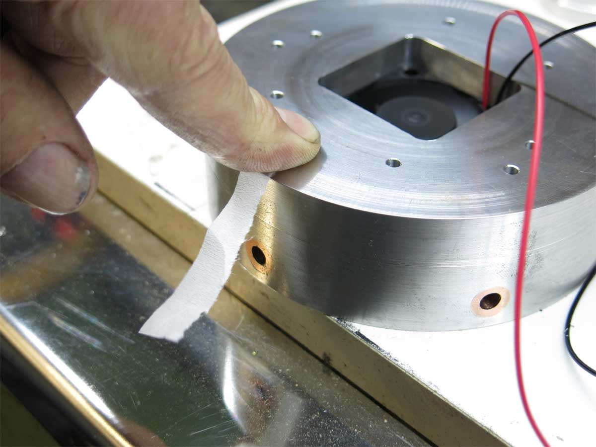
And a view of the heat tube holes where the air blows through under the leds.
I have no idea at all if this is going to cool very well in the light of reality but we shall soon find out.
The fan is in operation here blowing out a gail force wind, I wish. :person_facepalming:
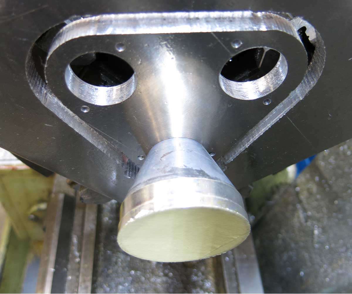
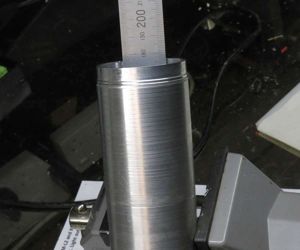
The next part on the agenda to be made is the battery tube.
The problem of battery holders was solved with a quick solution as time is rapidly running out. I had previously purchased in a group buy three battery holders which are 4S1P. I will be running two of these in parallel.
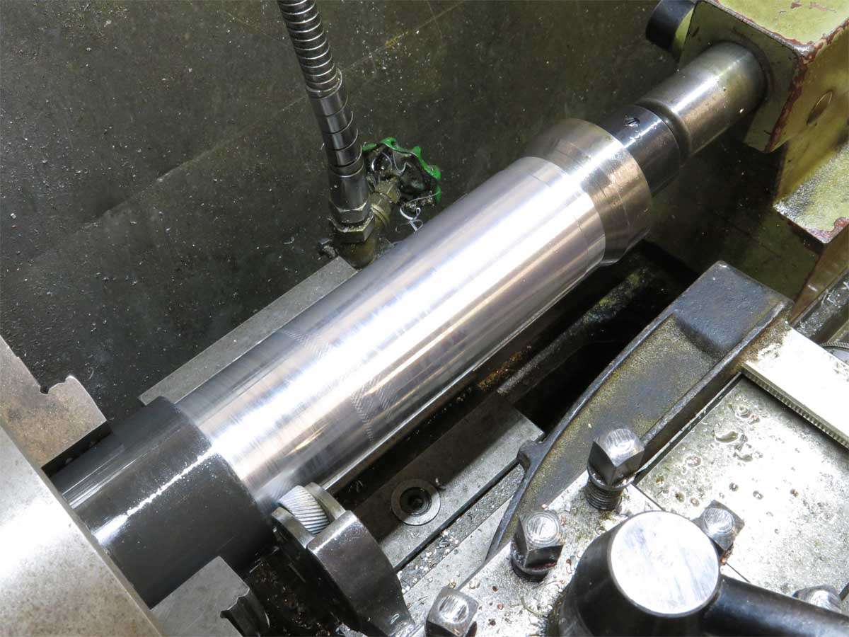
An old aluminium tailgate cylinder rod off cut was found to be around the right size.
This was taken to work to rough it as it would of taken me a week to machine this out on my lathe where at work it was quickly machined out during my lunch break.
The big lathe at work board this depth easily without chatter.
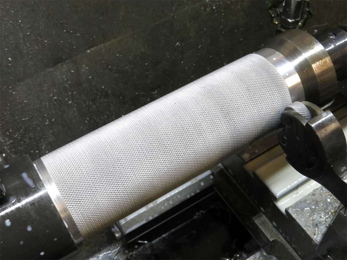
The rough outside was turned down to the same diameter as the Q8 battery tube and the knurling tool set up.
There is no drawing for this part as its just being made up on the go. The battery tube will be part of the naked design when its finished.
After a few anxious minutes which seemed at the time an eternity we had knurling.
At this point if I still drank I would of put the beer down and had a Scotch. I hope someone out there has one for me.
You have quite a lot of aero resistance already. If you can, pick a high-pressure fan. Also, I would try positioning the fan higher, I have a hunch it would work better.
I would also suggest machining the fan hole slightly deeper and putting a small heatsink at the bottom to add some fin area.
The fan is what was available quick as there is a time limit on the build.
As for sucking rather than blowing I think it will work better blowing through the holes as the intakes will be a lot larger than the outlets. Then again maybe not. I’ll just get it together and if more work needs to be done I’ll worry about it then.
On a side note I may try and taper the sides of the recess on top of the fan for more of a venturi shape.