Thanks for the comments guys and taking the time to follow the build.
About being precisely thought out, well some parts may be but other bits are blindly stumbled through.
Thanks for taking the time to peek in ImA4Wheelr. Your always welcome here. :sunglasses:
Its unfortunate l will not complete this build before the comps over. I’m heading off on holidays tomorrow and wont be back until next month. I will continue with the build then.
As that is why I said ‘nearly everything else’. They’re equal but sometimes dealt with separately… Like me and my son going to an F1 (or other) race. Austin, TX today!!
No finish for Ricciardo today. I hope you both had a terrific time.
I’ve also been to the F1 race here in Melbourne with the old man a few times. The speed they go is to me incomprehensible. I reckon they would leave a cats reflexes for dead.
I’ve managed to sneak a few hours out in the shed today so have got a little more of the light finished.
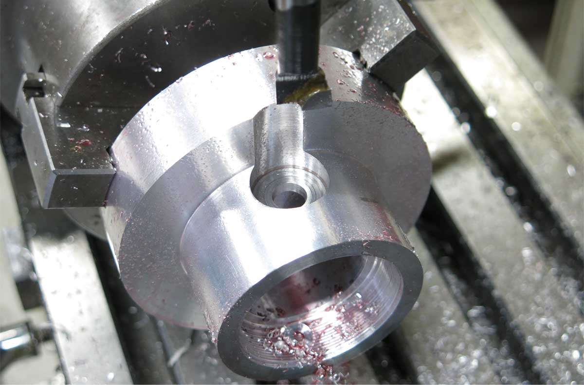
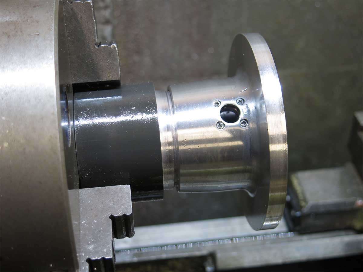
The head was placed back in the mill and the hole for the switch assembly bored.
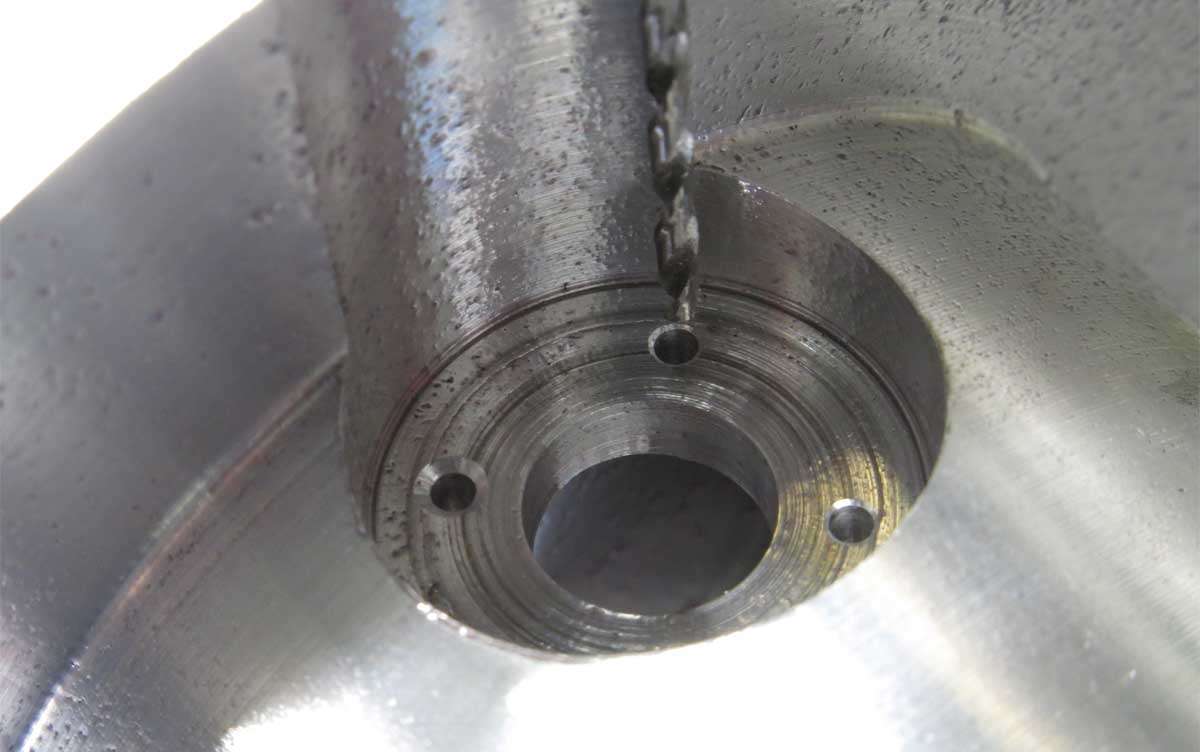
Four holes were drilled to screw the switch retain on. The drill bit here is 1.7mm or just over 1/16’’.
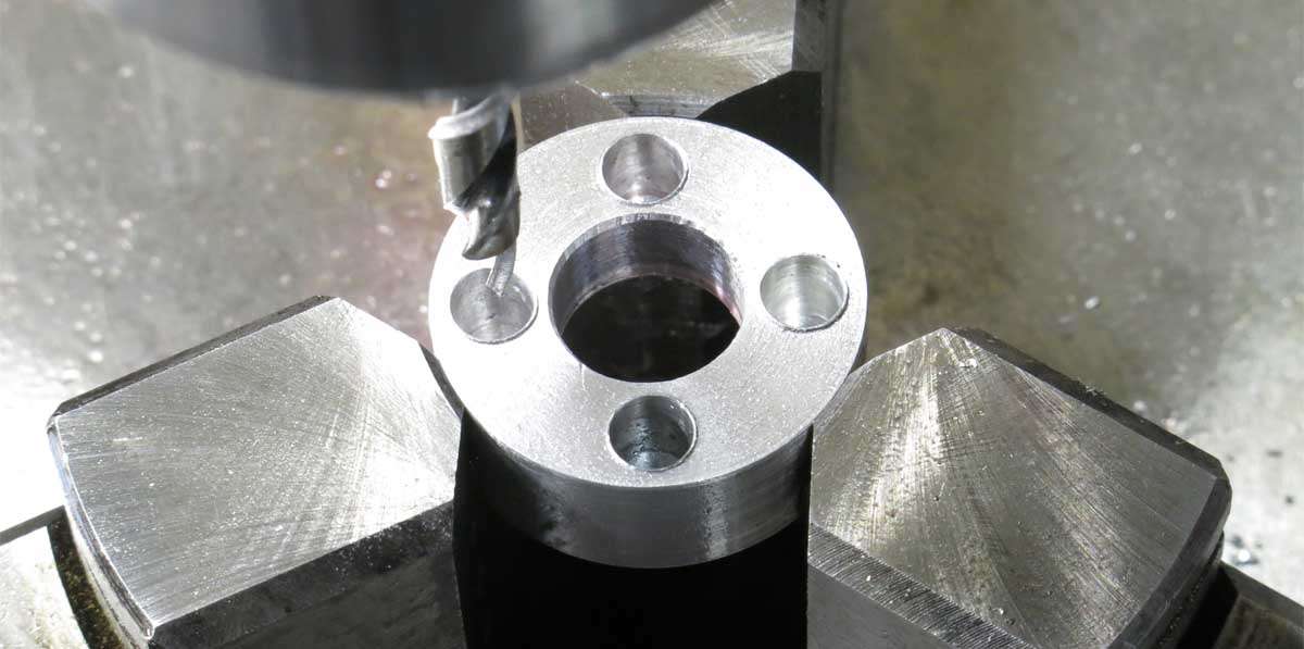
The swich retainer was machined up in the lathe and then placed in the mill to drill the four holes to match the ones in the head.
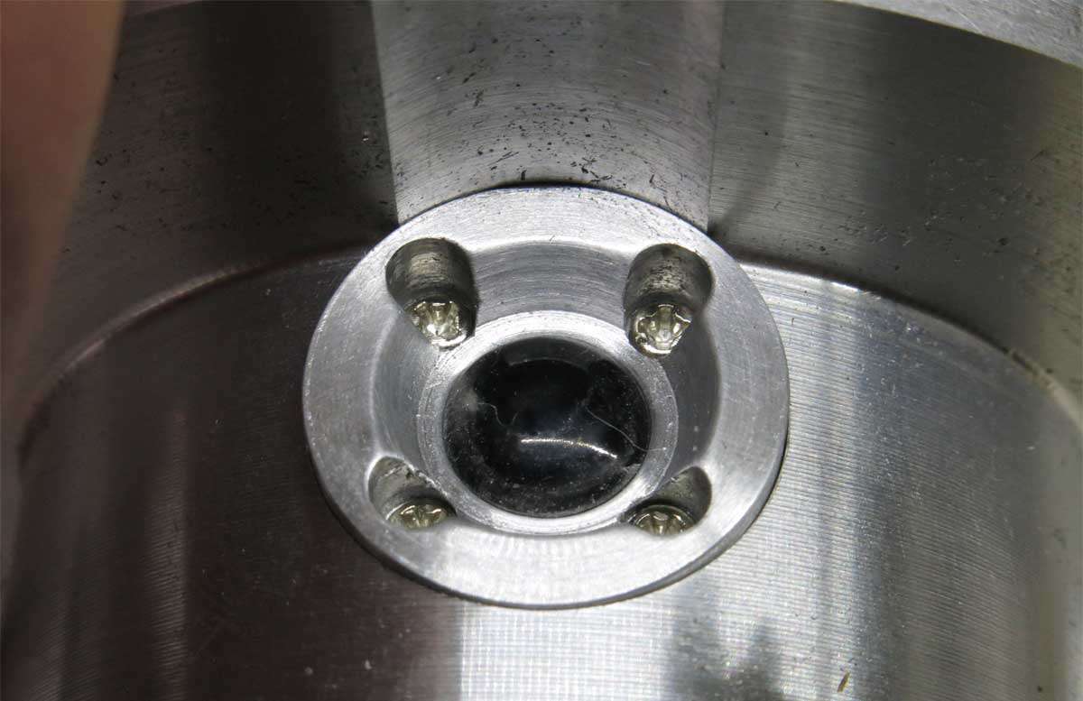
And here are the two pieces assembled together with four 2mm screws. No snapped taps this time.
The top of the head was slimmed down to 7mm in width.
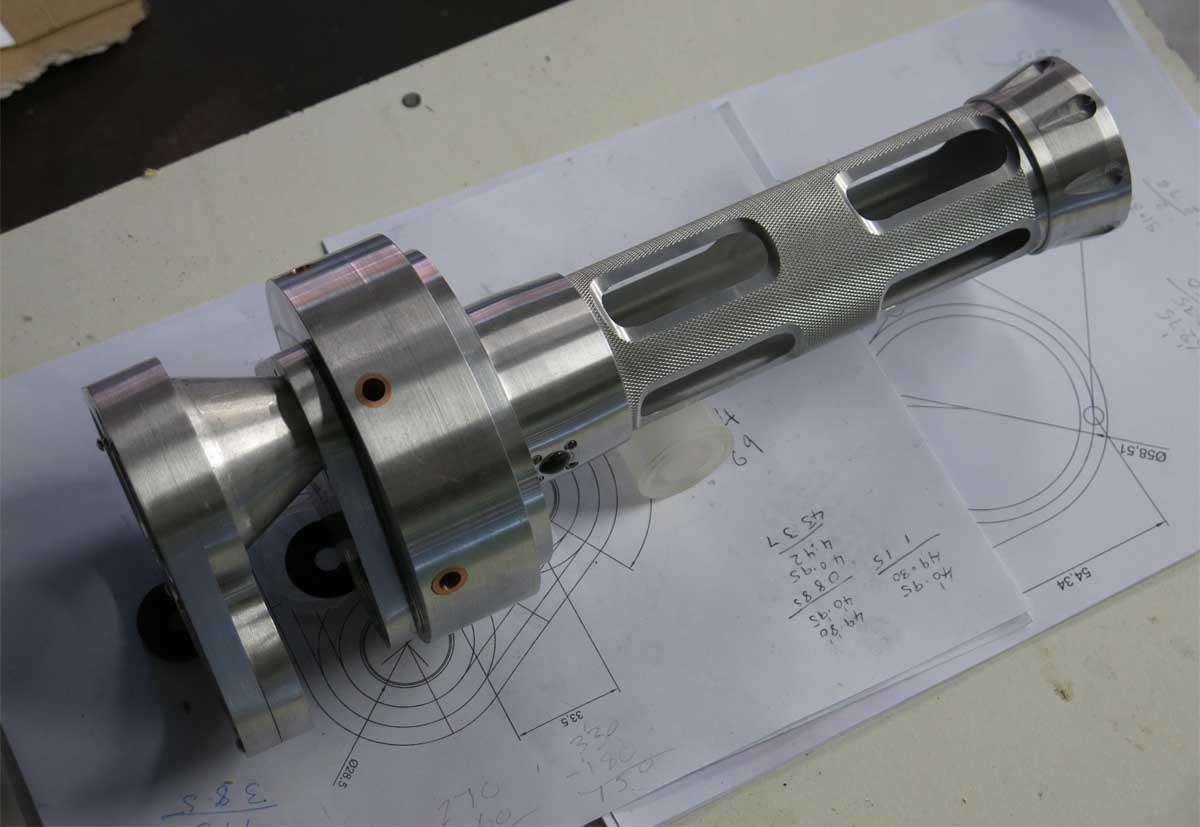
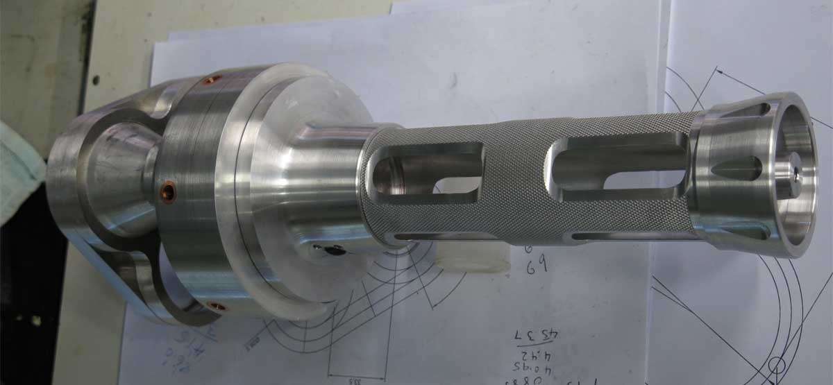
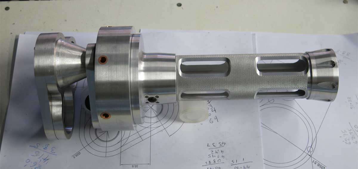
And a few pictures of a far from completed torch dummied up.
Dnf is back severely jet lagged and worn out after a whirlwind, non stop tour of China with an amazing bunch of people in an amazing country. The train topped out at 308 KPH and the party was documented by many confused Chinese passengers but that is another story.
Thanks for all the comments and work will continue on the light in the near future when the body is back to normal (no comments please :weary: ) and the chores around the house are caught up with, if thats ever likely to happen.
Theres no sorcery in this light TK but there is plenty of your sorcery in a lot of other lights around here.
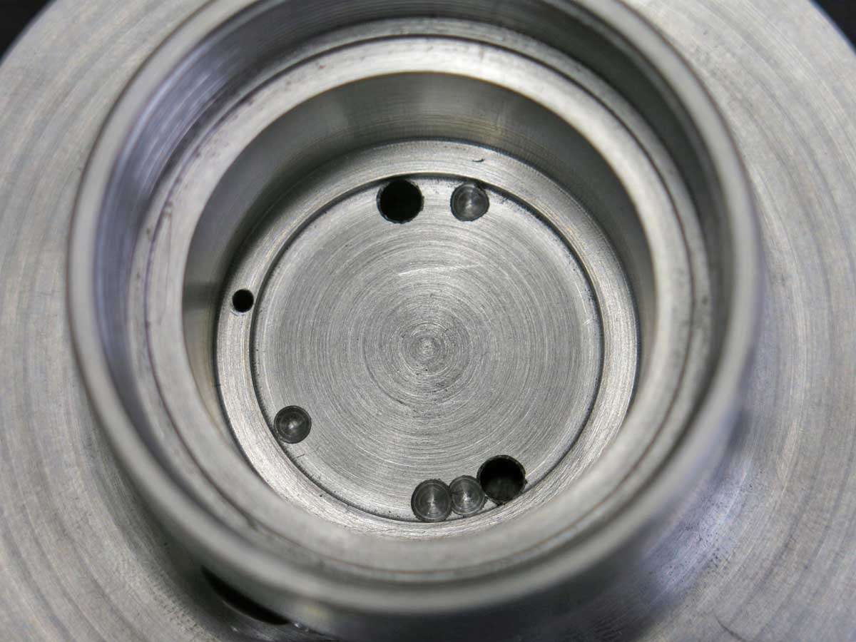
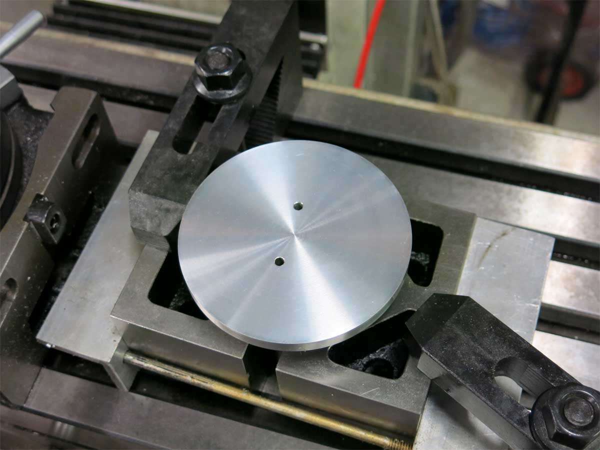
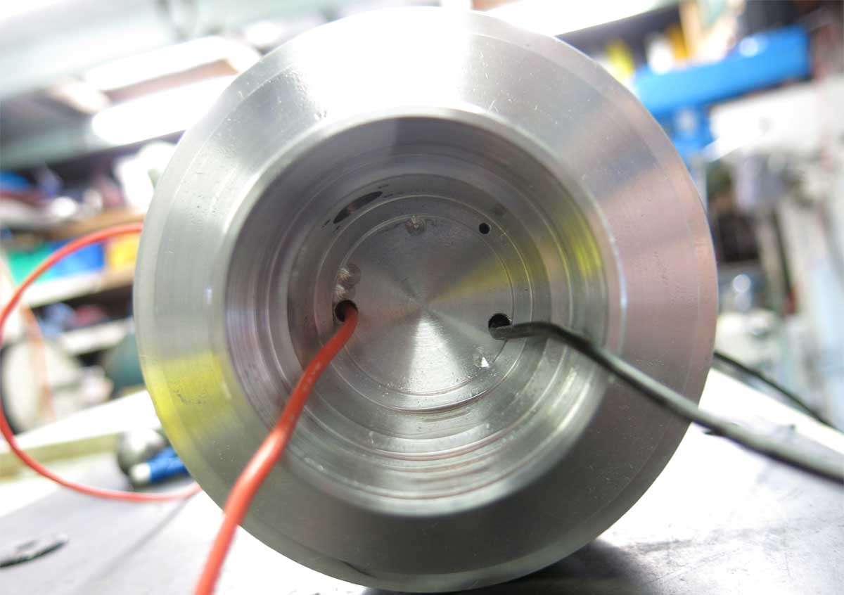
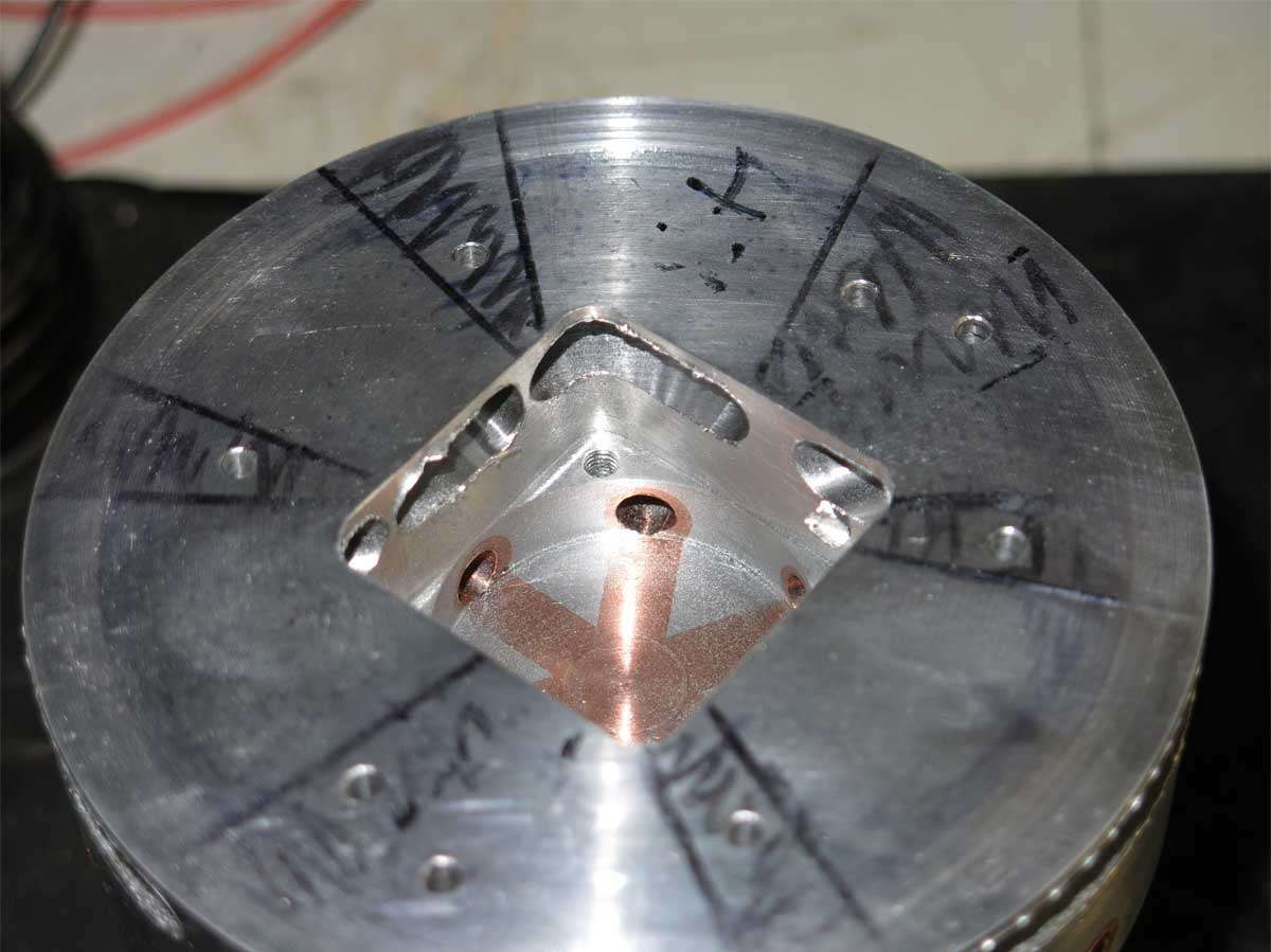
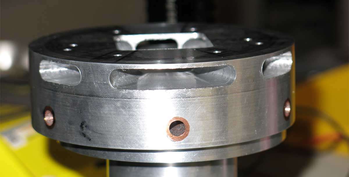
This picture shows where the driver sits. The two through holes are for the led positive and negative wires from the driver. The dimples are to make sure the driver doesn’t short out in these places.
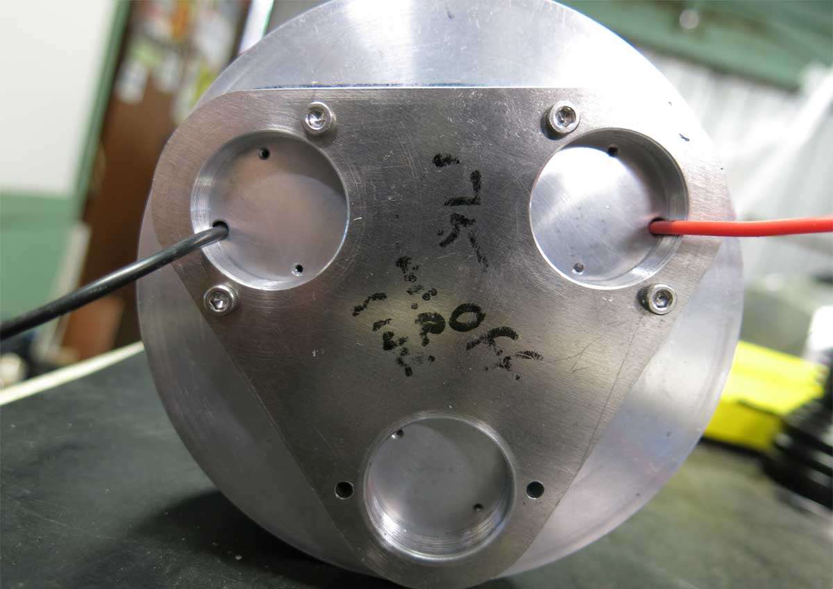
This is the opposite side to the above picture showing the two through holes. The wiring comes out where the fan is positioned in the next level of the head.
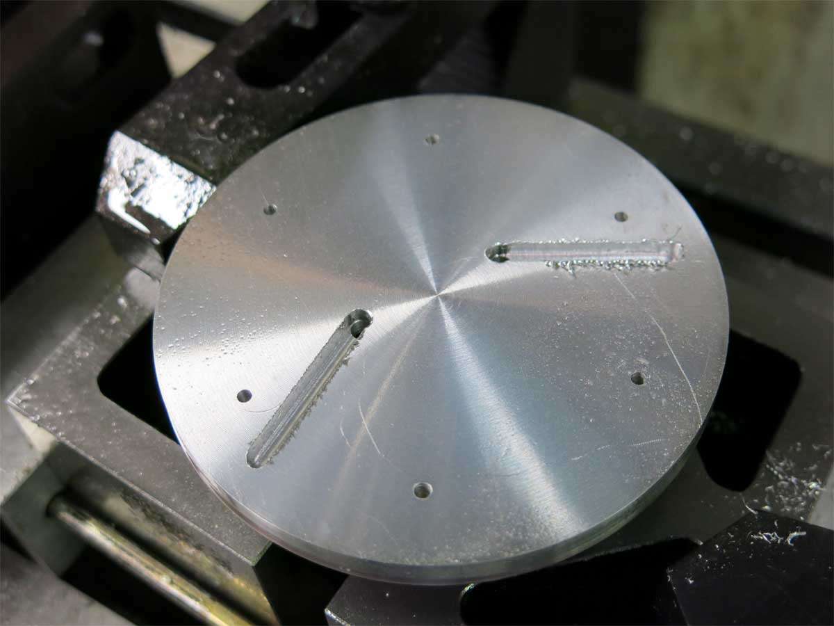
Two grooves were machined for the wiring to clear the fan area. The grooves end where the holes are for the wiring to travel through the fan housing and come out in the position of the negative and positive for the leds. Hope that makes sense.
The following two pictures explain a little better than I.
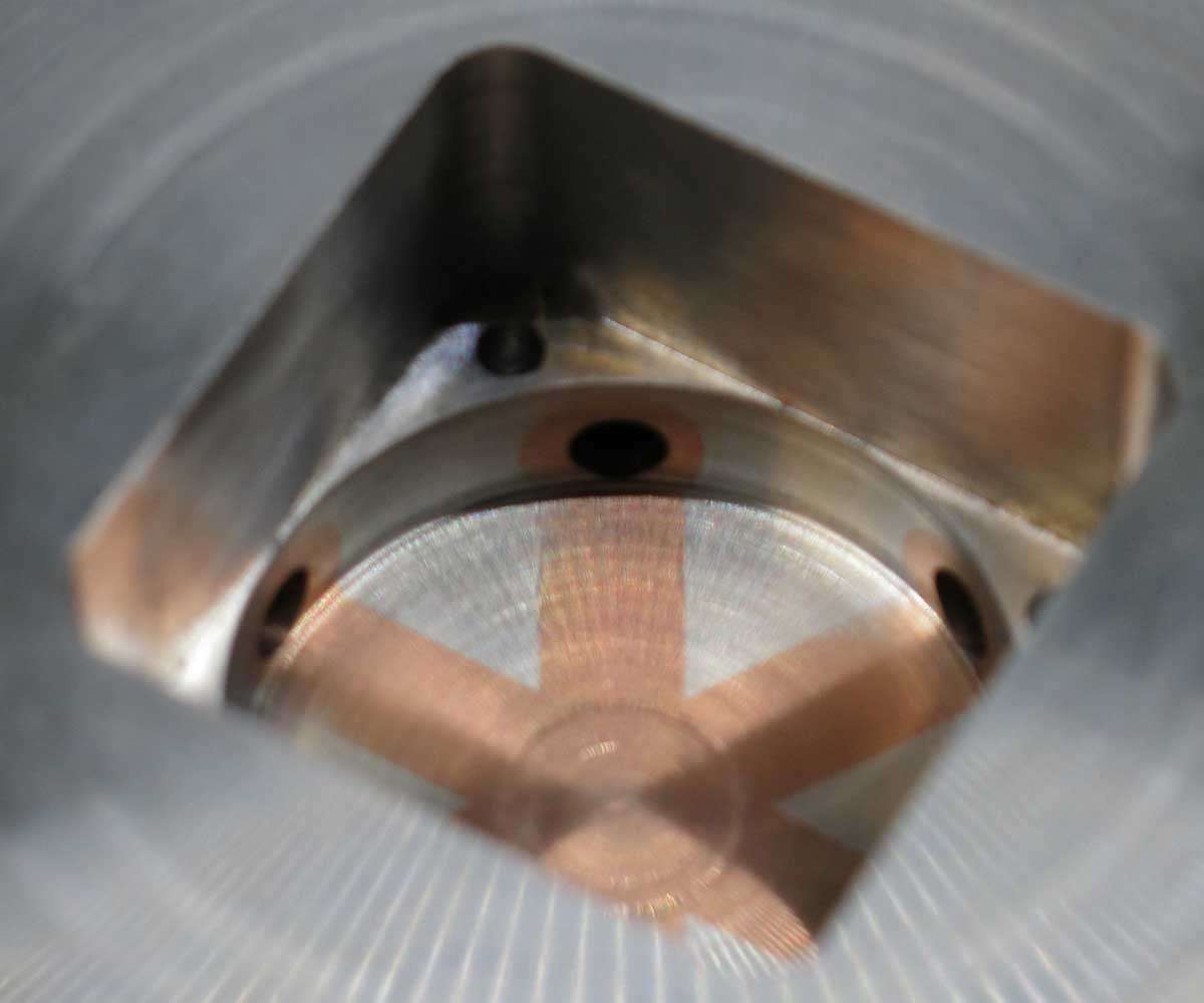
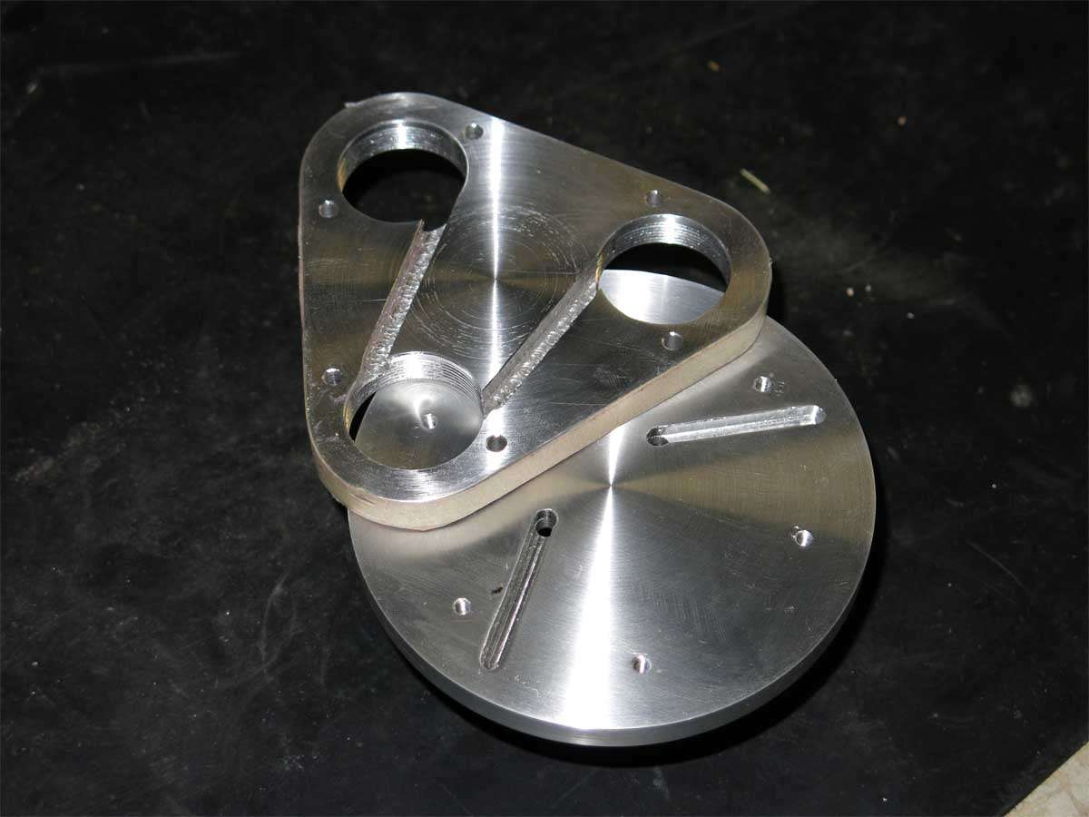
And to end this groovy session the plate where the reflectors screw into was slotted on the back to allow the wiring to connect the three leds in series.
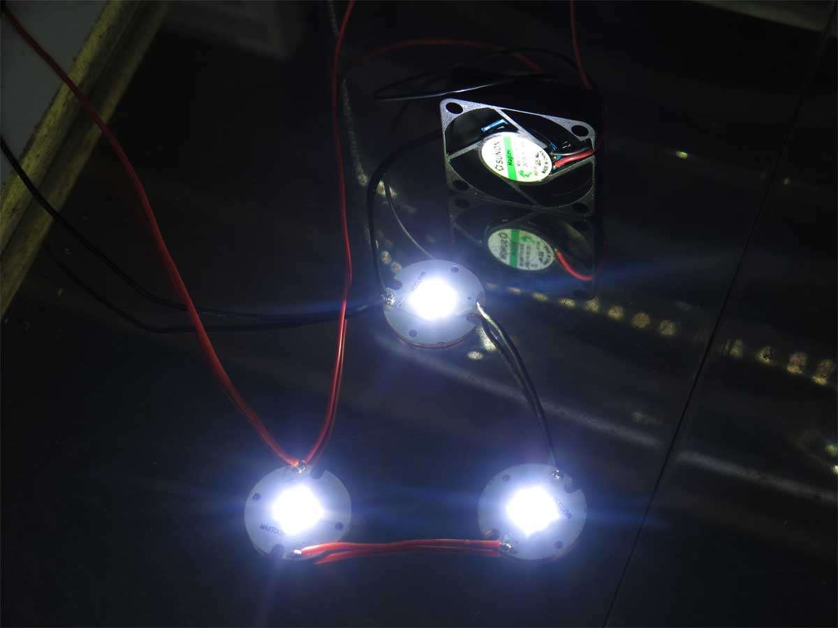
As proof of concept the wiring and leds were tethered together and fed some power. The voltage at the leds was 1 volt higher at 2 amps than calculated from the djozz testing chart. This was a good thing as the fan will be getting a higher voltage, hence spinning faster than first thought.
It is expected each led will have 6 amps on high when completed.
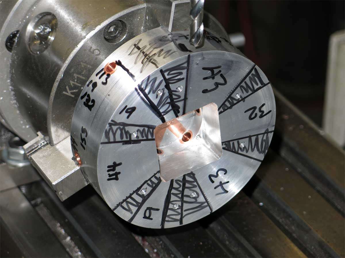
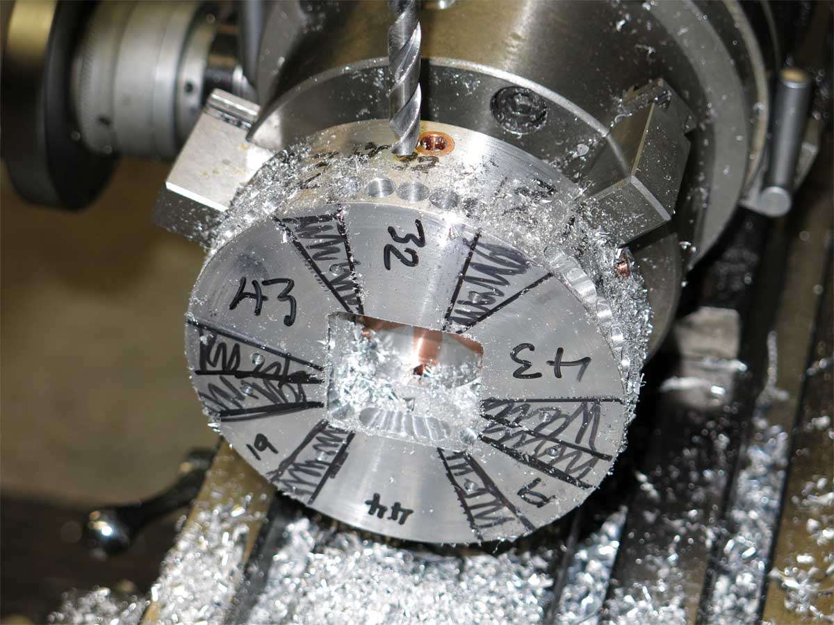
Next up was the slotting of the fan housing to allow air to travel into the fan and be expelled out through the copper cooling pipes.
A marker was used to mark the non machined areas and act as a map. I did not want to slot where the six through holes for the retaining capscrews and two wires travel through.
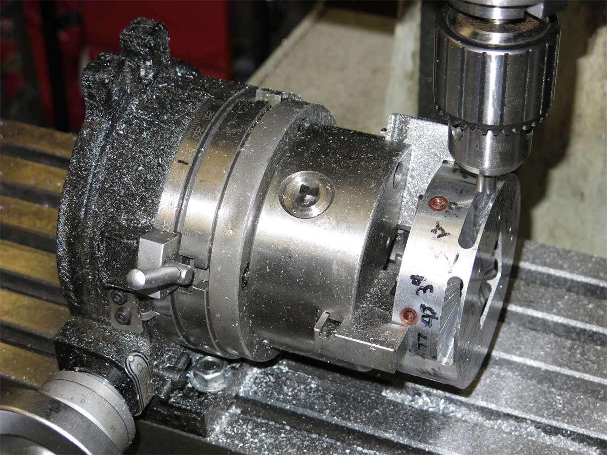
Lots of 19/64’’ holes were drilled.
The slots were then finished of with a 5/16’’ end mill.