I have a D4 MCPCB at home. I will measure it just tell me what dimensions you need. In D4 the screw holds the MCPCB and two legs of the optics resting on the screw. So if we make like D4S and same screw holding down the aux pcb you need to cut off more from the legs on screws. Maybe you need use longer screws also.
Edit: I think less leds are also enough. like 6 or 8.
Ummmmm… Yes, please!
looks great, a green would be nice to my green 18650. I hope price will be around 50$ or so but who knows…
Holey moley!
Just because you can draw something doesn’t necessarily mean it can be made.
Try snapping that one out of a biscuit. Nevermind routing out all the big holes.
I’d love me one of those boards to pimp my D4 :party:
I am in contact with Intl-outdoor so they should become availiable fully assembled from him
Cool.
Cool!
But I would like to choose my own leds of course, so I would not mind an upload on Oshpark too (or don’t they do such thin boards?)
Oshpark 2Oz are 0.8mm thin, this should be enough
on chineese fab on panel I would go to 0.6mm
also made a programming adapter for my future drivers
same order in 2 Oz!

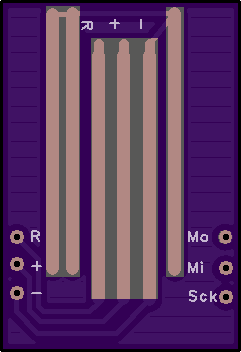
Fits those pogo pins from banggood
A part of me wants to call it overkill, but that aux LED board with its own regulator and balance resistors sounds sweet.
Lexel, can you clarify, which one is expected to become available assembled from intl-outdoor?
Thanks, :sunglasses: , ordered! 
has not been decided yet
The resistors and the LDO costs in serial production less than 20 cents so why not stick it on it
Of course a sort of LVP like I am planning on my tail boards would be possible as well, but that costs like 0.6$ more
Way to go!
But pogo pins do need some support, they are long, thin and bendy. Which is why I suggested a 3D printed support.
Perhaps a big dollop of hot glue might suffice.
Back in the day my kit was designed for ATE on a GenRad/Teradyne bed of nails, with guided probe for detailed stuff. Everything made extremely precisely and solidly.
Not necessary for a torch. Just a common flashing interface.
I love it
Thanks for the review, loving the aux lights!
I fear, you won’t have fun soldering pogo pins aligned with your design, lexel, something like this with a notch for automatic alignment might be better. Was still difficult to solder though, especially with iron, I was successful with hot air finally. But hot air might cause problems with a 2-sided design.

A SIM card connector (mini, micro, nano) could work, but is OTT. And no room.
Pogo pins onto vias or pads is the obvious way forward, at the moment.
This has to come, since MCUs will have no external pins to clip on to, even if there is keep-out area for a clip.
I’m hoping Hank might offer a flashing kit too, but I don’t know if that will happen. For now, I could stand to get some pogo pins (or really any pins) to put into my ribbon cable, since I haven’t had a chance to try out the flashing pads yet.
such a cool light, hope it won’t be too pricey. thanks for the first look
Really hope this will be available in the new white surface as well as a floody optic option!