Yes it works, solder across the back, Tab is ground. Same with the 4 pins in the rear of the Infineon, (underneath the FET) the large base is ground. It will all become clear when you remove the old FET.
Thanks, I removed the old FET and see what you mean.
I also readied a piece of 30 AWG Kynar wire to replace the trace that I ripped off of the board. :person_facepalming: It’s the one that connects the pin 1 of the FET to R3 and R4.
I’m trying my darnedest to kill this driver! I’ll report back in a couple days when a new FET arrives.
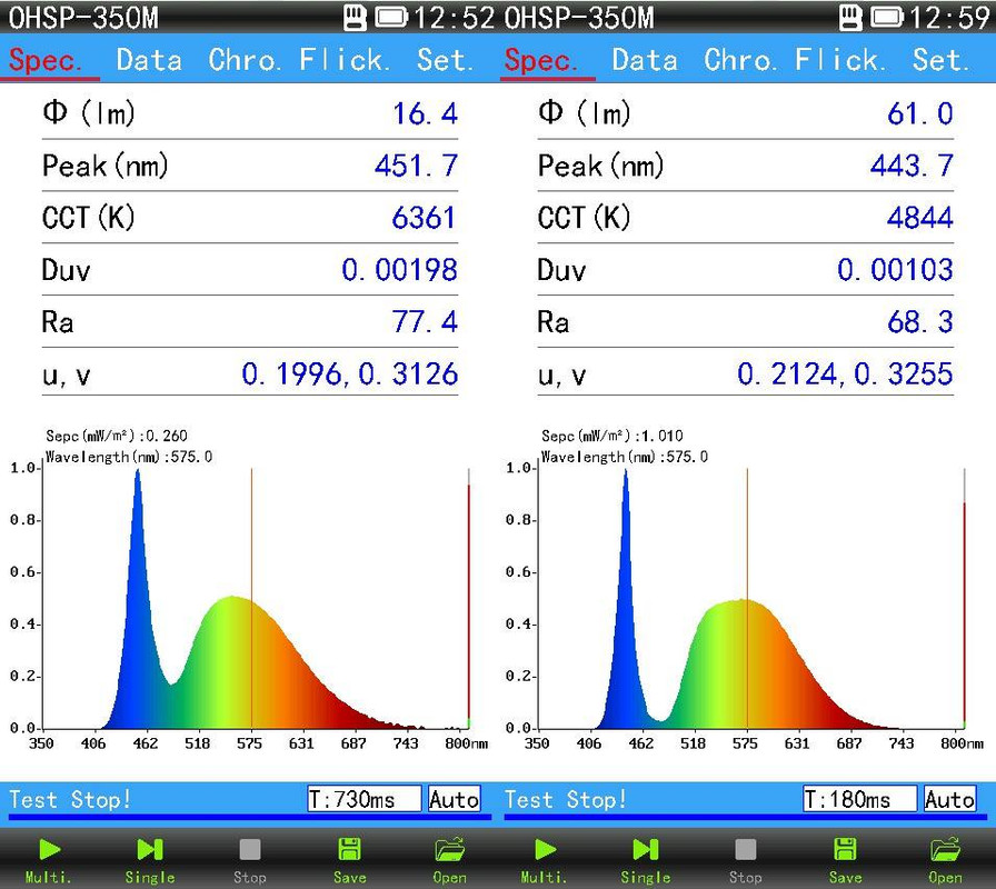
I reflowed Samsung LH351C emitters on my otherwise stock Emisar D4 with Nichia 219C LEDs that I managed to dedome from heat. I felt that my stock Nichia LEDs were tinted green. I thought that the Samsung LH351C would be better but they seem to have the same green tint maybe not quite as bad. Puts out 2400 lumens OTF at turn on, 2200 at 20 seconds, not very impressive and they seem to heat up just as quickly as the Nichia 219C, probably beacause of the lower forward voltage.
Are those the 5000K 90CI LH351C emitters from Arrow? That is a disappointing first result from this led, at this current a lower performance than 219C and not a great tint.
I keep hearing about tint issues with the LH351 but the ones I got from Arrow are very consistently pleasing, no green or rosy hues. I got the D model at 5000K and 80 CRI and the 40 I’ve used have been excellent. Price was very good as well at around $2.04 each shipped.
Oh, and Kawi? The large pad under the MOSFET may indeed be the negative lead to the emitter but it definitely is not ground! Let ground touch that and you’re in direct drive from the cell with no modes, bypassing the driver…
Just to be clear for those that are new to all this.
I got the new FET installed on the D1S driver but it’s still one mode.
I tested the switch and it’s good, and the driver acts the same with the switch removed.
For now, I put my D1 driver into the D1S so I can do some comparisons with the GT mini. I made sure to make my MCPCB solder joints flat and toward the outside of the board.
I probed around while I had both drivers out and the connections seem ok.
My trace replacement to pin 4 also tests good. It’s not touching pin 3 as the photo might suggest.
Earlier, I incorrectly referred to the bottom right pin of the stock FET as pin 1. It is actually pin 4.
I thought the dimple in the corner of an IC was a universal marker of pin 1. Apparently not?
BTW, Hank got back to me, and it’s $6 for a replacement driver.