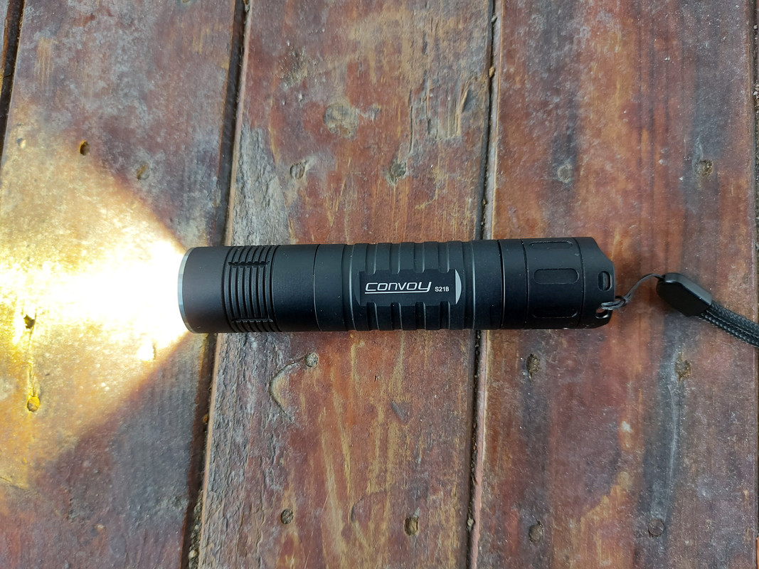
My S21B CULPM1 has a bit of a “petal” when looking at the beam. ![]()
My s21a also has a bit of a petal beam, but it’s a cslpm1. Doesn’t bother me much but I can see how it would others.
My S21B XHP50.2 just arrived.
S21A SST40, 5000K, 1700 lumen

S21B XHP50.2, 4000k, 2300 lumen
does the 8A buck driver use an NTC to control the temp? I’d like to remove it if possible. I wish the L21A had ramping of some sort as Turbo only lasts 3 minutes then back to 700 lumens.
Careful, the mcpcb needs the screws as the reflector doesn’t provide enough force on the mcpcb, it sits on a shelf. There’s been QC issues since Covid. Had a whole bulk order of C8+ units with dusty reflectors.
People need to stop complaining about the beam for these Osram leds as it’s normal across every brand. The Convoy lights have it, Noctigon K1, Sofirn SF47T etc all have the petal beam on a white wall. These leds are for long range use, can you notice at 200-500m away, no.
The centering ring can’t be any different as any force on the led could cause it to come off. These are quite small, that’s why it can’t use the snug fitting square centering rings.
Guys, i need your help to determine what resistor to order for purpose of lowering max output.
Driver is 17mm 5A 12group and i would need 4A and 3A (have 3ea).
I meassured resistor dimenssions 3.35x2.65mm roughly and written R010 which gives 5000mA now.
The story behind is that i’ve got colored S2+ Osrams and green is running great but yellow-orange and especially blue Osram is going to fry. My idea was to lower amps on blue to 3A and on amber to 4A instead of 5A originally.

If you stack two R025 in parallel that should give you 4A.
The closest you’ll get to 3A with a single resistor value is probably stacking two R033s (for 3.0303A), or an R025 and an R050 to get 3A on the dot.
Many thx oweban!
No probs - for reference, I use this:
R010 is 0.01 for the first value, then amps is 5, then hit Calculate - then remove the current and Power, and adjust the resistance value to the R-value you want ![]() write them all down and add up.
write them all down and add up.
It is normal that S21B XhP50 dont have spring from driver side?

I have sst40 and there is this spring but in XHP - i have 2 of this and there is no spring
I have the same
Thanks.
Calculating the (peak) sense voltage a driver uses is of help to determine how much current will go through a given resistor in it.
For the Convoy ∅17mm 5A linears with a 10mΩ sense resistor, V = I × R = 5A × 10mΩ = 50mV peak sense voltage.
So, since I = V / R you can calculate how much current for each resistor: R020 -> 2.5A, R025 -> 2A, R033 -> 1.51͡5A, R050 -> 1A, etc.
Power rating matters too, driver uses 1210 imperial size (3225 metric, 3.2 × 2.5mm), but if current is lower size can also be smaller: R020 or bigger value sense resistors (2.5A or less) could be 1206 imperial no problem guaranteed.
Thx Barkuti.
I just ordered a M21a with sst40. In the description it says the following:
Driver: 4 modes 0.1–3–30–100 / 12groups, max current output 6000mA,
Does this mean at 100% output the driver only allows the emitter and battery to run 6amps? I guess I’m asking, like a fw3a when on turbo runs a high amperage depending on your battery. Correct? Is this m21a constant current + FET or just constant current?
Artiet59, the drivers you mention are constant current linears, they use MOSFETs in triode mode or linear region. The principle of operation is like a gas valve (the MOSFET or MOSFETs) where the flow of gas (current) depends in how much the handle is turned open (MOSFET VGS or gate-source voltage). The driver MCU senses the current flow in the sense resistor, and tunes the MOSFETs VGS to limit the current flow accordingly. Of course, when the current flow is below the limit (battery too low, high emitter Vf, etc.) they limit nothing.
What you call “FET” mode is operating the MOSFETs in saturation mode, this is like opening the gas valve “all the way”. The current is then mainly limited by other reasons like spring, driver and battery resistances. If you can only operate the MOSFET blindly in saturation mode (open all the way), the only way to obtain lower modes is with PWM (quickly opening and closing the gas valve).
After checking out the thread CRX FW3A Mods & Teardown I see a driver with 8x 7135s plus MOSFET in saturation mode. Without wanting to be judgmental about the driver (great software I guess), it employs very outdated ways of doing the job. 7135s can only work at 350mA constant current, and so the only way to obtain lower modes is to PWM :facepalm: them. Honestly speaking, I don't see a reason to mix 7135s with a MOSFET onboard, as you can obtain lower modes by directly PWMing the MOSFET (and thus saving all the space occupied by the 7135s).
I prefer to always go regulated, but of course I know how to fine tune the sense resistor of a driver in case I need to lower or to increase the maximum current.
The FW3A has a very fine tuned driver, the Lume1 for FW3A/C/T - Constant Current Buck Boost + FET Driver with Anduril - Now for Sale! (not :X cheap, though).
Barkuti- thank you for this info. Fantastic job drawing comparison with an engine which I understand functionally better then a electronic driver. But I think I’m catching the drift of what you’re saying. One question- because I don’t know- what is the benefit of running PWM on the mosfet itself versus running PWM on the 7135’s? What exactly are the 7135’s, resistors?
Good explanation and simple-to-understand analogy for us who are not that well-versed in electronics.
However, regarding the PWM — based on my visual inspection (I’ve tried out the 4-mode and 12-mode driver [not the original Biscotti 12-mode]), both the 4-mode and 12-mode driver do not produce PWM (at least when I use the “shine light through a small fan” method). Does this mean it doesn’t use PWM for lower modes (in contrast, I can detect “fast” PWM with a flashlight that uses the Biscotti 12-mode driver, when set to lower brightness levels; but not in the lower brightness levels of the Convoy 4-mode (5A/6A) & 12-mode (5A/6A) driver… Or does it also use PWM but just too fast to detect? I remember Simon mention that these drivers are “constant current” without PWM (although I’m not that well-versed in electronics whether constant-current and PWM can co-exist?)
I’m also curious if PWM FET only drivers are more efficient than a 7135 based driver up to 3-5A.
I hesitated to buy some replacement drivers from Simon with the FET only layout that Artiet59 listed.
LEDs are more efficient at lower currents, so using PWM to lower the output of a 7135 is slightly more efficient than PWM on the FET in saturation. In actual practice, the difference in efficiency is probably negligible when compared to something like a buck converter.