For reference, courtesy of CPF member Download:
For reference, courtesy of CPF member Download:
The board I used is Dx sku 7612 and though from the description it sounds like it is in parallel with the single mode board. It is, but only in the sense that the processor circuit on each multi-mode board is in parallel with the drive circuit connected to the amc 7135 chips and yes, it does work. That part is straight from the Oldlumens/Techjunkie and will work with any 7135 board, single, multi, whatever. Just run two leads from Vbatt; one to led, and one through the reed switch to the board. Power is always on to the led but current only flows when the Vdd pins on whatever board you are using are switched on. This part is tested by many others and verified most recently by me just yesterday.
Afaik, all 7135 chips are have the same outward topography, that is, they all look the same aside from printing, and the pins are all in the same relative position. Apply more than 2.7V to Vdd, and 350 mA can flow through the chip from led- to ground. This is the trick. If you’resoldering skill is up to it, you could concievably make an 8-chip sandwitch with no board at all.
I say the 7135 chips on the processor board are not in use because they aren’t. In my circuit, there is no lead from led- to the chips on the processor board, only to those on the slave board. My circuit is only using the throughput of the slave board, 1.5A.
Yes, this is the method I referenced for using the leds to lower the voltage to the board and got me to wondering about other possibilities. Someone had mentioned combining this idea with The Oldlumens/Techjunkie master/slave mod but I could find no other reference to such a combination. Like I said, since the high current of the leds does not flow through the multi-mode processor, why not just put all the leds in series and use a much smaller resistor to lower the input voltage to the multi-mode processor?
Okay, I have read in Download’s thread mentioned above that his idea would work with lower Vf xml and xpg chips only if a high wattage resistor were used to step the initial fresh battery voltage down to ~ 3.6V per cell. Maybe an inline .33 ohm 5W resistor connected to an on-on switch. This would have the benefit of reducing the resistance needed for the onboard resistor for the multi-mode processor. A fuel guage would help note the correct time to switch out the large resistor.
The questions being raised are to the point and are welcome as they will lead to solutions. Does anyone have any ideas about measuring the current in the control/enabling part of the circuit. Has anyone put a clamp meter around the switch wire leading to the master board in an Oldlumens/Techjunkie setup?
Looking at the Add tek data sheet for the amc 7135 sot-89 it says that the current consumed at the Vdd pin is 200 micro amps or .2 mA. This is for each chip on the board, so a 1.4 A 4- chip board would need .8 mA (.0008A)and an 8x 7135 board would need 1.6 mA shared between all of the Vdd pins on the board. It also says that the sot-89 package, which is the one commonly seen on drivers, can handle ~ 700 mW or ~ 2V excess at 350mA output.
This equates to a max of about 5.3 V at the output for a single led with a Vf of 3.3V. This is all speculation on my part so far but for a board to drive 4 xpg from a 4-cell Li-ion:
4 x 4.2 = 16.8 V
4 x 3.3 = 13.2 V or 3.6 V excess. To get the excess within spec of the chips, I would need to lower the hot battery voltage by 1.6 V. 1.6 V / 1.4 A = ~1.1 ohms and 1.6 x 1.4 = 2.24W equals the power consumed in the resistor. Note, this is power that would otherwise have to be burned off by the 7135 chips, so it is no more wasted than it would be otherwise.
On the processor side of the circuit, the input voltage would need to be lowered from 16.8 down under 6V or a total of 10.8 V. So 10.8V / .0008A = 13.5 k ohms and the wattage would be 10.8V x .0008A = 9mW, not a problem for a 1/10 W surface mount resistor.
So what happens when the battery level drops to ~ 3.7V per cell or 14.8V?
14.8V - 13.2V = 1.6V and we no longer need the 1.1 ohm resistor. A fuel guage on the battery would be helpfull in determining when to switch out the resistor.
For the processor, 14.8V - 10.8 V = 4V and the driver is still within spec. At about 13.5 Vm, the voltage to the processor would drop to 2.7V and possibly shut off. In reality, under load, Vbatt would drop immediatly and such a high value resistor might not be necessary. If under load Vbatt was only 4V per cell or 16V total, then the resistor would be: 10V / .0008A or 12.5 kohms and the input voltage to the processor would drop to 2.7V when cell voltage was at 12.7V or ~3.2V per cell. At this point the leds are already begining to be underdriven. This happens whether cells are in series or parallel. The ideal would be to have the leds begin to dim and have the resistance set to kill the lights nearer to the low voltage cutoff of the cells ~3V.
The push behind this idea is that for bike lights, which often have the lamp in one location, the switch by your thumb, and the cells in a third location, having wires with several amps running though them(as is needed for parallel circuits) is not the best solution. Having your light all in one body would solve this at the expense of having to take one hand off the bars to switch modes; not for me on rocky singletrack.
I really like your ideas tho I dont quite understand half of it.. but if you use 4 cells and 4 leds, why not just go direct drive or..
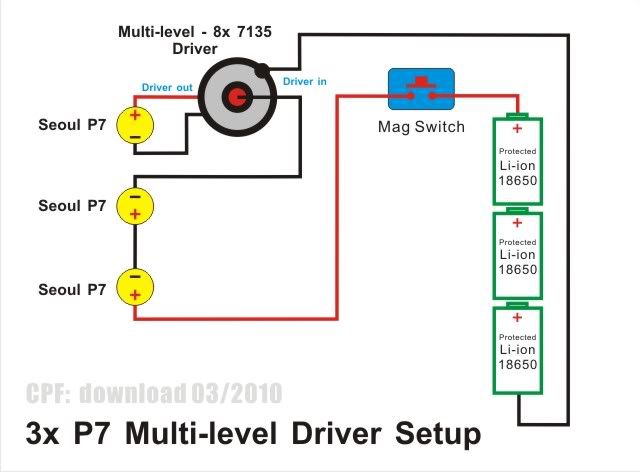
If it really is possible to use the AMC chips in series like shown in the picture above, why still use a driver board rather than just wiring up the AMCs without processor and stuff?
If you are referring to Downloads diagram(by the way, thank you ChicagoX for posting that image) what it shows is the need for reducing Vbatt(the voltage from the battery, to the processor not the 7135 chips. The diagram in the method used by Oldlumens/Techjunkie shows that the processor can be powered separately from the LEDs using a low current through the processor on a master board to control the led current on the slave boards.
In a nut shell, modes and runtime. I don’t need high output grinding slowly up hill but coming down I need to see every root, rock, and rut, and I need to have hours of run time without extra batteries. DD would work but have no modes and lousy run time. Actually, while I was searching info on these chips I ran across some Soeul stars with two 7135 chips and a diode. The first piece of info in the data sheet for the Amc 7135 reads “no external components needed”. Another tidbit was that the T0-252 package for this chip is rated at 1000 mW which would take care of the higher voltage drop I need without using a 1.1 ohm resistor or extra switch.
Actually, 700mW is the max without additional heatsinking. So with a good enough path to ambient(I’m talking ground tab soldered directly to solid copper, not the measly foil on these board, and definitely separate from the led heat sink, even the smaller sot-89 might handle the load. Before I do that I want to verify the input resistor value for the processor. Anyone ever heard of a 10k-15k ohm linear pot? If I start at 15k and reduce the resistance until the processor goes poof I’ll know the minimum value needed.
Actually, a reverse audio taper would give me more accuracy at the high resistance end of travel. I checked and these are not cheap. Better would be a 10k-12k ohm resistor in series with a 5k or 3k linear pot.
Indeed, a resistor is needed if using Download idea to drive 3-4 XMLs in series,
otherwise, too much heat may be shed onto the 8x7135 driver board & may burn it out.
I had a build a while back, tried out different resistors. Different battery & XML vfs may need fine tone the resistors
Example here:
I advise against using a resistor for the logic supply voltage (MCU and AMC7135s). The current of these can vary quite a lot (e.g. with PWM), which would result in a wildly hopping supply voltage.
Alternatives: Voltage regulator like 7805, available in various form factors, including TO-92 and SMD. Or resistor and zener diode.
The data sheet for 7805 indicates other components unnecessary but schematic shows capacitors on input and output. Are they needed with a battery power supply?
Very much agreed. When the logic is idle, it could be drawing half or less of the rated current - this would cause it to see a much higher voltage. Resistor and zener is the way to go. Choose a 5V zener and a, oh, I dunno, 1k ish resistor… That will allow the logic to pull a couple of milliamps when/if it needs to…
PPtk
Ok, it makes sense that the input voltage would fluctuate to the attiny pwm chip if I just use a resistor. What makes the resistor + Zener preferable to the “black box” approach of the 7805? Is it more efficient, cleaner, or what? Thanks for this input. I enjoy going outside the box but I fully realize this makes me vulnerable to mistakes. I’ll throw my pride under the bus for knowledge anytime.
So I found a half dozen 78L05 in a SOT-89 package(same as 7135). Operating voltage 6.75V-26V. Output current is 100mA. Atmel chip draws .24 mA and four 7135’s draw .8mA so there should be plenty. I thought I would desolder the 7135 closest to the Atmel chip,“stack” in on on of the others, and put the 78L05 in its place. It would not be soldered to the pin pads other than ground, I would have to jumper across/in place of, the reverse polarity diode from the 78L05 in/out pins. Again, the data sheet says no additional components needed, but could signal bounce from the pwm chip cause problems in the 78L05? Should there be a .1 microfarad cap from the output of the 7805 to ground?
The 78L05 is a good choice. The resistor and zener isn’t better - its just cheaper ![]()
I wouldn’t worry too much about cross-talk and radiation from the PWM into the regulator. Yes, you should try to cobble a .1uF cap on the output though. If there’s room, a .1uF and a .01uF, in fact.
I only paid $.50 each for 6. Where would the .01 cap go? Also across the output? Or one on the input, one on the output? Saw a diagram with .33 microf on the input and .1 on the output. How critical are the values(other than voltage capacity)?
Values aren’t super critical for an application like this. You don’t really need cap on the input, but the .1 and .01 on the output (in parallel) is a good idea. If you don’t have any .01s, just the .1 will probably be fine.
I’ll be waiting awhile for the 78L05 chips to arrive but in the meantime I’m working on a drawing that shows how this works. I’ve studied close ups of a few different boards and I like what I see. In each one that I examined, it appears that the 7135 chip closest to the processor and led+ pad could be replaced with a 7805 SOT-89 voltage regulator. I would need to cut the traces leading to the other 7135 chips and jumper the led+ pad to the input pin on the 7805 and the output pin to other side of the reverse polarity diode. An smd cap across the output pin to the ground pin and done I’ll try an make the next post with fewer words and more pictures. Check back in a week or two. This could be a way to use these boards with more options on battery voltage.