Ever since I became aware of the Sanyo UR16650ZT, I have been very interested in this cell. 17650/17670 cells are very popular with those that have 2xCR123A lights, and wish to use them with a single li-ion cell, but do not wish to risk boring out the light to take a 18650 cell. Likewise, they are popular with Maglite mod’ers, who use these in tri-bored, shortened D cell Maglites to make a compact light that still has enough voltage to power multiple LEDs or hot-wire bulbs. I myself was interested in using these in a tri-bored, triple XM-L MagD.
The problem with the 17mm cells is that they have not received the same level of development as 18650 cells have recently, and so capacity remains low. 1600mAh pretty much seems to be the de facto standard capacity for 17670 cells – for instance, the AW 17670, or the more recent Eagletac cell of the same size. Ultrafire have advertised 17670 cells of 1800, and even 2100mAh capacity, but considering some of their capacity claims for some of their other cells, I take that with a pinch of salt. As such, when I saw that the Sanyo cell was said to have a minimum capacity of 2100mAh, max 2200mAh, by the manufacturer, despite being an even smaller 16650, I really wanted to try these.
I spent a while looking for suppliers for protected versions of these cells, only to find that the few suppliers there were all stated that they had to be supplied by the hundred, or even thousand. Even fewer actually had these cells in stock. I eventually found that these were available from www.intl-outdoor.com, that they sold them individually, and had stock. I ordered three of these straight away.
A Quick Aside
A few people have issues with intl-outdoor, and I won’t say that I haven’t been effected. However, in my few dealings with Hank at intl-outdoor, he has never been rude, and has resolved my problems.
Along with these Sanyo cells, I also ordered three of the protected Panasonic 3100mAh cells. Like others, I received cells with protection circuits that cut out at too low of a current. These wouldn't allow anything close to a 2C discharge. Hanks new supply of cells with better protection circuits has not come in yet, so we don’t yet know how or if he will offer any deal on these for people who bought the previous cells.
What I can say is that one of the Panasonic cells that I did receive had quite a large dent in it, and I only received one of the three Sanyo cells I ordered. I reported this to Hank, and he instantly refunded me for the dented cell, and sent out two more Sanyos. I and others have since received further deliveries from Hank packed in boxes rather than padded envelopes, so damage in transit should be less likely.
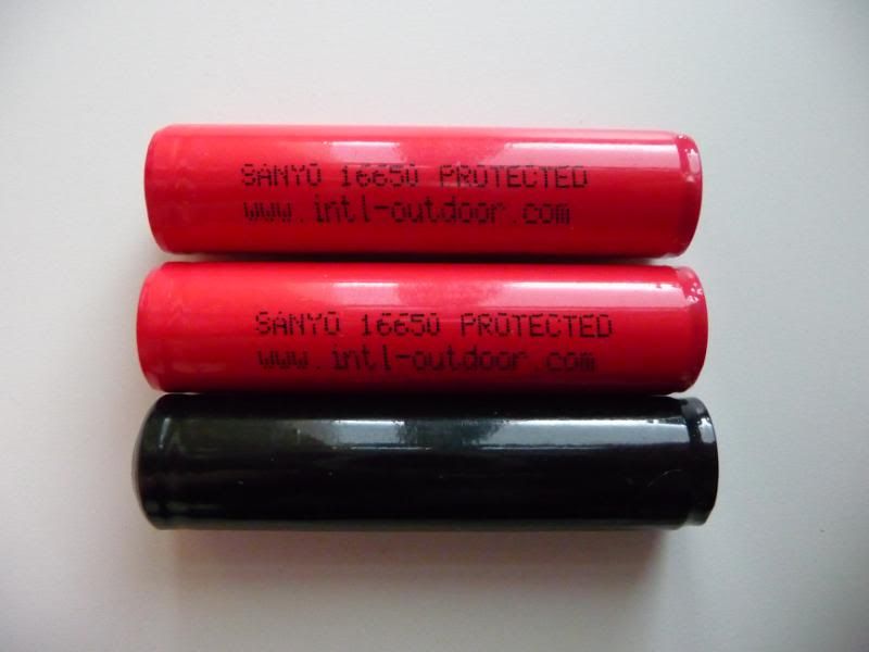
Of the two Sanyo cells that I then received, one was red wrapped (this is the newer cell, and the same as the one that I received with my original order) and on was the older black wrapped cell as shown on the intl-outdoor webpage. One of the reasons for conducting this test now is to see if these cells perform the same, despite some differences in construction.
Testing equipment
A quick re-cap of the equipment used for testing: -
I will (normally) be charging cells with an iCharger 106B+, and discharging and testing internal resistance with an iCharger 208B. Two chargers are used for speed and convenience – one cell can be charging while a second is being discharged. I use the same charger for each step to ensure consistency in conditions between tests, so that results are comparable. I use iChargers specifically because they have an adjustable CV setting. This can be set as high as 4.30V – perfect for these cells.
However, for these tests, only the 208B was used. I had great difficulty getting consistent internal resistance readings with these cells. Once I achieved a consistent, low IR reading, I decided not to move the cell from charger to charger, but instead left the one cell attached to the same charger, and did all the charging and discharging steps one after another. I then attached the second cell, and did all the testing on that cell on the same charger.
Voltage is measured with a Precision Gold WG 020 multi-meter, dimensions with a Precision Gold digital calliper, and weight with a Neva digital scale stated to be accurate to 1/100th of a gram.
The base of the cell is attached to the charger via a 12” 16AWG cable with a large, strong magnet soldered to it. The positive button is attached via a magnet (if it adheres well) or via a crocodile clip. With these Sanyo cells, due to lack of magnet adhesion, and an inability for the crocodile clip to hold on to the button, I ended up threading a small split ring through the button’s vent holes, and then attaching the crocodile clip to the ring. An odd set up for sure, but it gave a lower and more consistent IR reading.
Results at a glance
http://industrial.panasonic.com/www-data/pdf2/ACA4000/ACA4000CE301.pdf
|
|
Cell 1 (red) |
Cell 2 (red) |
Cell 3 (black) |
|
Initial voltage |
3.97V |
3.97V |
0.00V (1) |
|
Measured length |
69.14mm |
69.22mm |
69.82mm |
|
Measured width (max) |
16.91mm |
17.04mm |
17.11mm |
|
Weight |
39.79 grams |
39.88 grams |
39.72 grams |
|
Internal resistance at initial voltage |
195mOhm |
195mOhm |
N/A (1) |
|
Capacity from storage down to 3.00V |
1377mAh (2) |
1384mAh (2) |
N/A (1) |
|
Internal resistance after storage charge |
200mOhm |
201mOhm |
N/A (1) |
|
Capacity from 4.3V down to 3V @ 0.4A |
Terminated prior to CV phase (3) |
N/A |
N/A (1) |
|
Capacity from 4.25V down to 3V @ 0.4A |
1913mAh |
1923mAh |
N/A (1) |
|
Capacity from 4.2V down to 3V @ 0.4A |
1834mAh |
1832mAh |
N/A (1) |
|
Capacity from 4.2V down to 3V @ 1.0A |
1806mAh |
1803mAh |
N/A (1) |
|
Capacity from 4.2V down to 3V @ 2.0A |
1777mAh |
1767mAh |
N/A (1) |
|
Capacity from 4.2V down to 3V @ 3.0A |
1710mAh |
1686mAh |
N/A (1) |
|
Capacity from 4.2V down to 3V @ 4.0A |
1334mAh |
1241mAh |
N/A (1) |
(1) Cell number 3, with the black wrap, was dead on arrival. Assuming that the protection circuit had tripped, I placed the cell in one charger after another trying to reset the circuit. Approximately half my chargers wouldn’t even recognise that there was a cell present, and just showed an open circuit. Roughly half indicated a bad cell or other error. A couple of chargers tried to charge the cell, but it didn’t jump up to 2.50V (or whatever the trip voltage of the protection circuit may be) – the voltage was increasing from 0V upwards. At this point, I put that cell aside.
(2) This is rather a higher value than I would have expected but is no doubt due to the higher than normal initial voltage on receipt of these cells.
(3) As HKJ found, the protection circuit does not appear to have been made with the UR16650ZT in mind – if you set your charger to charge to a voltage of 4.30V, the protection circuit will trip, and the charge terminate, before the charger enters the CV phase.
At a CV setting of 4.27V, the charger enters the CV stage, but doesn’t get down to 1/10th of the original charge rate before terminating. As the charge progresses, and the voltage fluctuates, prior to the current stepping down, the voltage may peak high enough to trip the protection circuit.
At a CV setting of 4.26V, the CV phase got down to approximately 0.2A – 1/5th of the original charge rate.
I was finally able to complete the full CV phase of charging at a voltage of 2.5V.
Construction
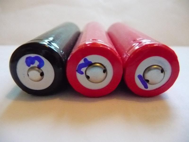
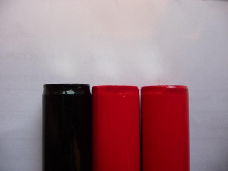
As per the above images, the two red wrapped cells have a common mid sized button, while the black wrapped cell has a very small button. Using the cells in series, or in lights with physical reverse polarity protection, should not be an issue. Magnets preferred to adhere to the shoulder of the cell rather than the button, leading me to conclude that the buttons are made from aluminium.
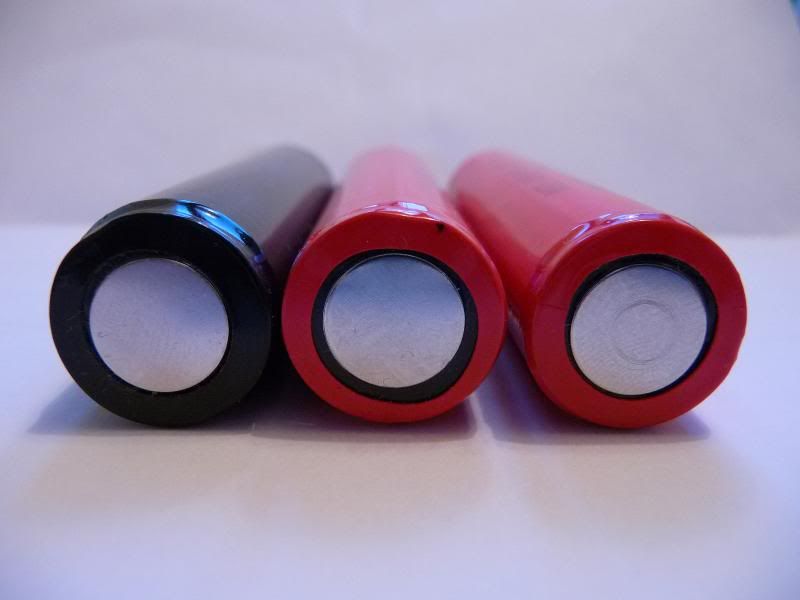
The base of the cell is a metal plate, so wear and tear should not be an issue. The black wrapped cell's base extends further than the two red wrapped cells.
The wrap of all three cells is the hardier vinyl type, rather than the brittle tape style.
Light compatibility
|
Light |
Characteristics |
Fits |
Functions |
|
Olight M20 |
Wide tube, spring at head, sprung plunger at tail cap |
Yes |
Yes |
|
SWM T20CS |
Short tube, dual springs |
Yes |
Yes |
|
Jet IIIM |
Wide tube, tail spring only |
Yes |
Yes |
|
Fenix TK15 |
Two-piece tube – narrow at head Short tube, short spring at head |
Yes (4) |
Yes |
|
Fenix TK11 |
Narrow tube, tail spring only |
Yes |
Yes |
|
Eagletac G25C2 |
Wide tube, sprung plunger at head and tail (minimal travel at the head end), physical reverse polarity protection |
Yes (4) |
Yes |
|
Nitecore IFE2 |
Narrow tube, physical reverse Polarity protection |
Yes |
Yes |
|
Fenix T1 |
Light intended for use with two CR123A only |
Yes |
Yes (5) |
(4) Obviously, the width of the cell was never going to be an issue here in terms of the cell being too wide. If anything, there could be issues with the narrow cell leaning over and being out of alignment with the lights contacts. This did not appear to be an issue with any of the light however. However, the cell was an issue in a couple of lights due to it’s length. Both the TK15 and G25C2 seemed to need more force to tighten the tail cap down than the other lights, and I believe that this was because they were tightening down against the battery.
(5) The light flickers rapidly on high mode, and is not as bright as with two CR123A cells. However, this is most likely just down to the reduced voltage of a single li-ion cell, as compared to the two CR123A batteries that the T1 should be run on.
Charger compatibility
|
Charger |
Fits |
Functions |
|
4Sevens single bay |
Yes |
Yes |
|
Trustfire TR-001 |
No (6) |
Yes (6) |
|
Ultrafire WF-139 |
No (7) |
Maybe (7) |
|
Ultrafire WF-188 |
Yes |
Yes |
|
HXY-042V2000A |
Yes - snug |
Yes |
|
XTAR WP2 II |
Yes - snug |
Yes |
|
Pila IBC |
Yes - snug |
Yes |
|
Jetbeam/Sysmax Intellicharge i4 |
No (6) |
Yes (6) |
(6) The cell will not sit flat in the cradle – the cradle is a fraction too short – but the cell’s positive button still makes contact with the charger’s positive terminal, and charging will proceed.
(7) The cell will not sit flat in the cradle, and may not make contact with the chargers positive terminal. The cell I tested had a slightly off centre button. Where the button was closest to the side of the cell, it would make contact with the charger. Where the button was furthest from the side of the cell, contact could not be made. On the whole, probably best to assume that this cell is not compatible with the WF-139.
Internal resistance
|
Cell |
Voltage |
Internal resistance |
|
Intl-outdoor 16650 #1 |
3.97V (as received) |
195mOhm |
|
Intl-outdoor 16650 #2 |
3.97V (as received) |
195mOhm |
|
Intl-outdoor 16650 #3 |
N/A |
N/A |
|
Intl-outdoor 16650 #1 |
3.73V (storage charge) |
200mOhm |
|
Intl-outdoor 16650 #2 |
3.73V (storage charge) |
201mOhm |
|
Intl-outdoor 16650 #3 |
N/A |
N/A |
|
AW 17670 #1 |
3.72V (storage charge) |
105mOhm |
|
AW 17670 #2 |
3.72V (storage charge |
105mOhn |
|
Best-in-one 17650 IMR #1 |
3.86V (as received) |
80mOhm |
|
Best-in-one 17650 IMR #2 |
3.86V (as received) |
77mOhm |
OK, the IMRs are only really a fair comparison in terms of size, not performance, but these are the only cells I have in this size range. I had hoped to get hold of a couple of Eagletac 17670s for comparison, but haven’t been able to get these shipped to the UK.