Maybe i can take some better pictures of the wiring layout of my 9xt6 for you when i get home?
Let me know.
But it does sound like there is a driver issue here.
Maybe i can take some better pictures of the wiring layout of my 9xt6 for you when i get home?
Let me know.
But it does sound like there is a driver issue here.
Thank you for the helpful replies! I think you both might be right. If those 2 LED’s that lit up were the formerly non-functional ones, then it would make sense that the driver is the problem and not both of the LED’s. As to the wiring, thank you FMcamaro, but the picture you have in your review was perfect already ![]()
I didn’t want to file a complaint once I saw that the wires were cut, because it seemed like an easy fix. I shouldn’t have had to repair even that, but I didn’t mind so much because I was eager to see this thing working. Either way, Ric emailed me a couple hours ago and said this:
Hi Gen1three ,
I think it might be the driver problem. Are you able to take the driver off to replace one, If so , i will send you a new driver to fix the problem.
ThanKS
Ric
*
Well, I really don’t want to file a complaint now, because he is attempting to make things right. Again, I still shouldn’t have to deal with this because the light should have been tested after being assembled. But seeing as how it took me a couple days to notice that only the center 3 LED’s were lighting up, I can’t really blame them if they didn’t notice either.
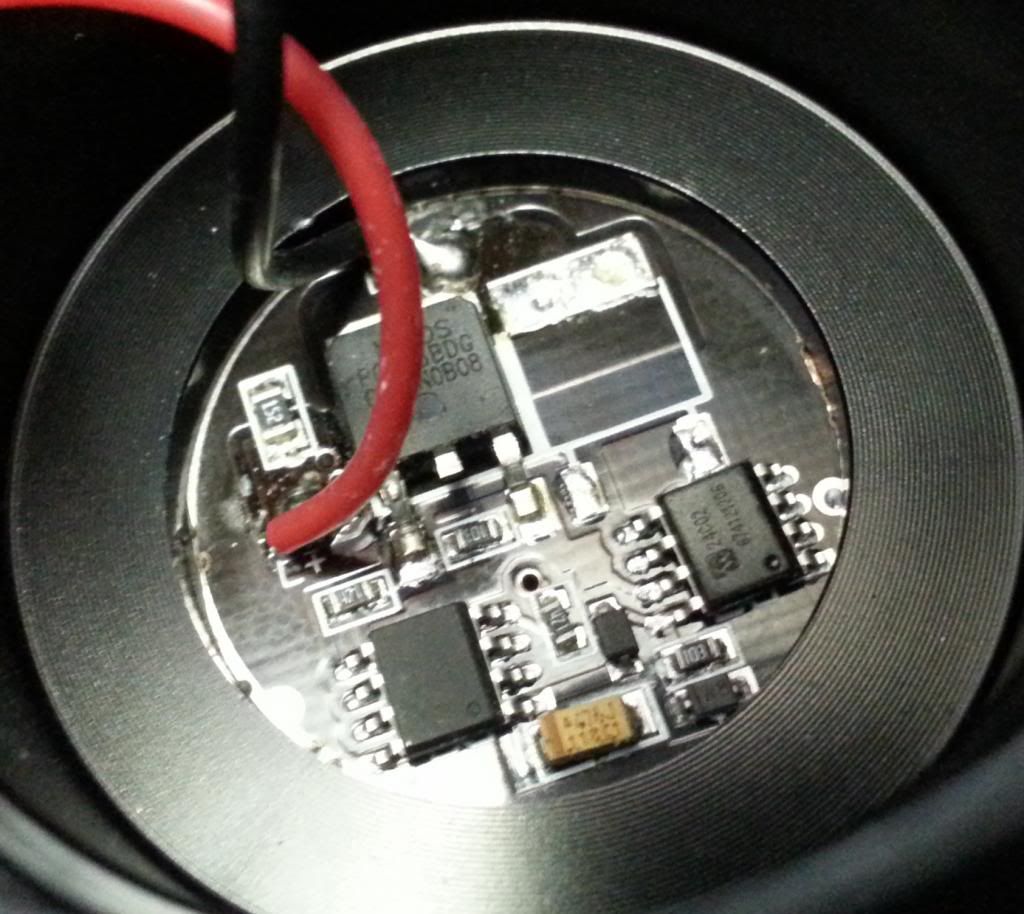
Anyway, I told him I wanted to get some input as to whether people thought it was the LED’s, wiring, or the driver that was the problem before he sent me a driver that may not fix it. Now, I am beginning to think a new driver might be the best course of action. I lack a tool to remove the driver though (note the 2 holes). Here is the underside of the driver:
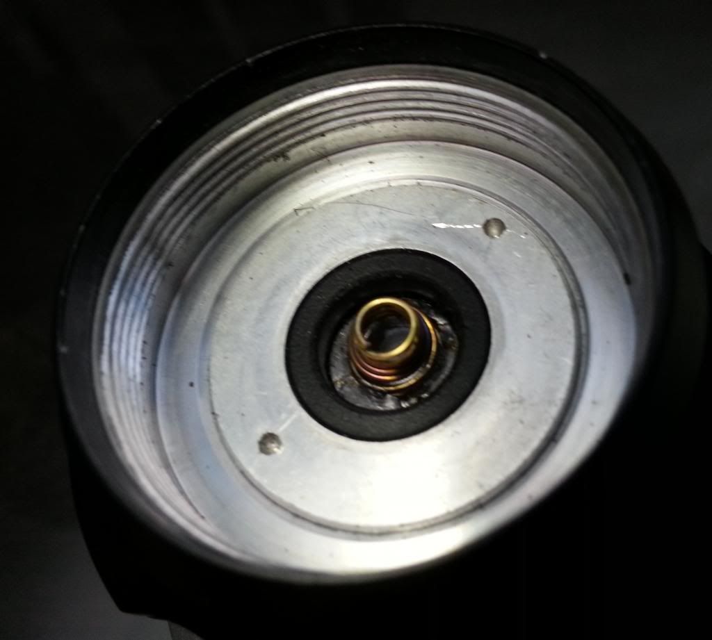
This is the topside:
Is a driver swap as simple as using the proper tool to unscrew the old one and soldering on the wires to the new one? I feel like I should order some better, thicker, wire and replace all the wiring while I’m at it. Also, do you guys know of some good thermal adhesive paste like the white stuff that they used to stick the LED’s? Even though the LED’s are pretty much held in place by the reflector, it would be nice to secure the loose ones.
A pair of snap ring pliers will be able to unscrew that alum holding the driver in place. If i remember from the posts in my review it was just sitting in there, should be easy to do.
https://www.fasttech.com/p/1200101
The LED’s are thermally glued on using Fujik
https://www.fasttech.com/p/1049304
IF your going to start doing mods, might as well get a bottle.
if you didn’t already, you might put 2AA in a battery holder that has leads and test each emitter individually
Awesome. Thank you for the suggestion. I’m going to order both of those. And I’m glad they’re both fasttech links :). I’m currently waiting on some batteries from them and some random odds and ends. They shipped out fast too, no pun intended. I don’t really foresee myself getting heavy into modding, but I might do a little here and there. I also just recently purchased a ton of random stuff from other sites too so I’m sure I can find a use for those items.
I have read “Fujik” quite a few times on light forums.
Why do people prefer it?
Does it have better heat transfer than other options out there?
What would be the difference between Fujik and something like Arctic Silver?
Is it because of a lack of electrical conductivity from silicone based thermal pastes? But in that case, there might be a ton of other options right?
The Fujik is just another brand.
Theres two different types
Thermal GREASE, which is comparable to the arctic silvers of the CPU world.
https://www.fasttech.com/products/0/10000468/1049305-fujik-heatsink-thermal-compound-20g
And thermal GLUE which is what i linked to you before.
The glue type products will adhere the LED stars where the grease will not.
Arctic Alumina is the comparable one to the Fujik that i posted before.
Its just a different brand. If you want to use the same stuff that’s on the flashlight now your looking for the fujik glue. Its way easier to work with.
Just don’t use glue or alumina on your CPUs!
Good point… I haven’t been to Harbor Freight in a few years, so it might be a good excuse to go. Thanks!
That’s nice and cheap… and potentially useful for other stuff. So there shouldn’t be a problem with a direct contact on the LED? Thanks for the link!
Ahhhhh… Thank you for the clarification! That makes a lot more sense now. Gonna definitely order some Fujik.
I can’t see where the above mentioned black wire goes. Please make some pictures of the LED wiring from different angle.

Both of those black wires are soldered onto that LED as indicated by the picture below. The orange dot represents where they are soldered together onto the LED.

It might still be a little difficult to see how they are soldered together there… but there appears to be good contact. Also, since the central 3 LEDs are still functional, there should be good contact there. The negative wire comes off the driver and is soldered onto LED “1”. Another black wire then connects “1” and LED “2”. This happens at the orange dot. Next is 3, then 4, etc.
Looking at that wiring, I'm going to say it is the problem. The wires are supposed to wire them in series, and I don't think that is what you did. (May be wrong)
I modified the picture. It may need to be refreshed if it doesn’t show the alterations.
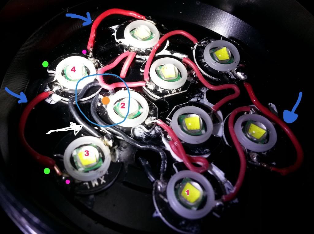
The wires marked by the blue arrows were the ones that were clipped and that I initially replaced. It was pretty obvious where they were connected, so I just replaced them accordingly. The white arrow marks the re-soldered black wire that firelight2 suggested. I don’t think I wired it incorrectly, but it’s been a while since I’ve taken electricity and magnetism in Physics so it all seems pretty foreign now.
Ok, are your LEDs wired like this?

P.S. Have I won the award for crappiest paint drawing yet? :P
There should be no branches (two wires connected to the same side of an LED). You have at least one branch in the red wires. You need to wire them like Scaru has drawn. There should be one wire going from the + of one LED to the - of the next LED.
Edit: Make sure the red wire coming from the driver goes to the first LED + and the black driver wire goes to the last LED -.
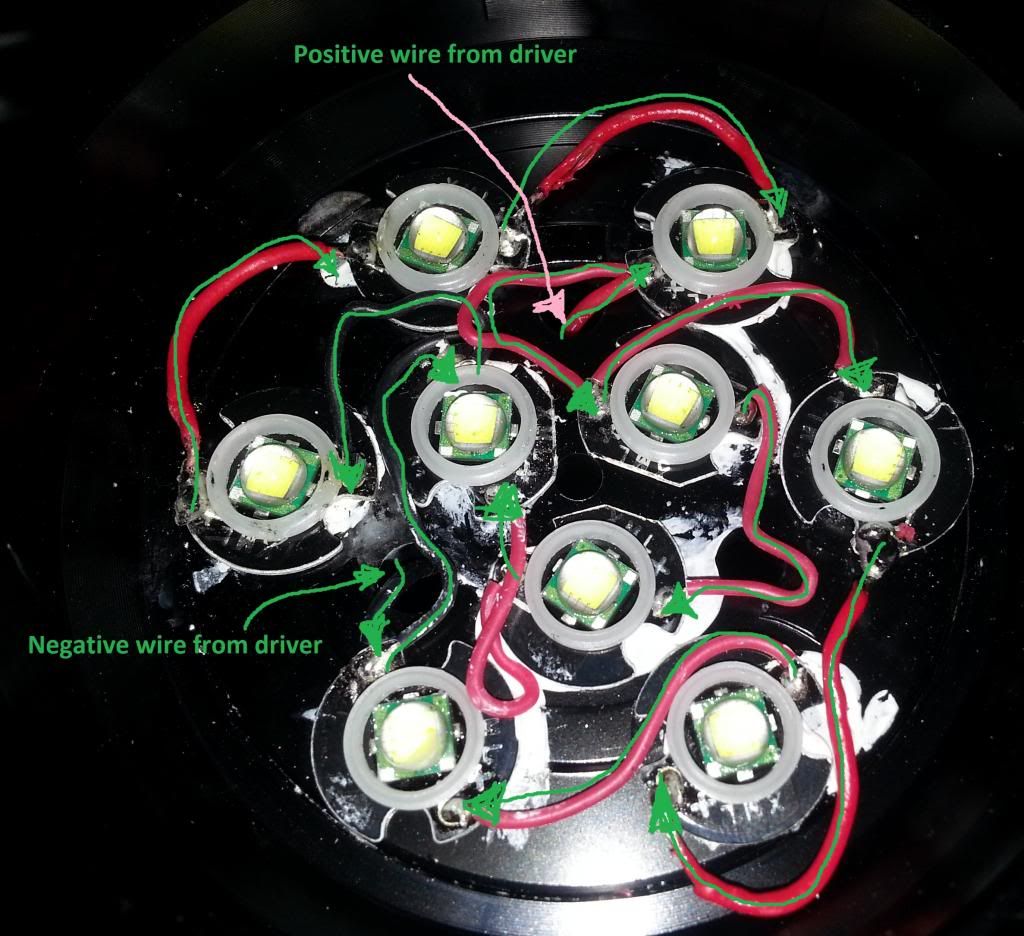
No his wiring is right, if I remember correctly there are 3groups of 3 parallel.
And this is what I can see.
This would also make clear why just the 3 in the middle worked.
What is status quo? Does it light up?
The wiring is in the same configuration that I received it in. This is a very crappy picture of the basic wiring:
Haha, I think my pic might be worse than yours now scaru… although yours does have elliptical LED’s…
Ok, if it is supposed to be 3S3P does your circuit diagram follow this? (Your drawing confuses me :P )

What is the actual problem? Which LEDs light up and which not?
The wiring seems visually correct for me.
Haha… yeah my diagram confuses me too even. But yes, it appears that it follows your wiring configuration scaru.
The problem is that currently only the central 3 LED’s are lighting up now. But prior to that, 7 of them were lighting up.
I think scaru is correct
the led that is furthest to the right has a wire coming off positive and going to a positive
even if they’re supposed to be 3s3p, they wiring is incorrect
instead of drawing on the picture, I suggest recreating the way it is wired in a diagram that is easier to read (like scaru’s)
Wiring is right! I see 3s3pi have marked groups with colors

The furthes right goes direct to driver just with a short visit at the other led