You can lift the MCPCB up away from the base (too much heat transfer with it still touching, makes soldering difficult) and unsolder the wires without removing the cover plate.
edit: I don't know what kind of board they use with the MTG2 version, curious to see if it's the same style as the XML.
If I decided to attack this, is there a way to make the driver step up to higher amperage? Would like to see it realizing a little closer to it’s full potential…not looking for 9A but…ok 9A would be fantastic! LOL (Serial #9, order number compressed to 9 according to numerology, so why not 9 amp?)
But seriously 5A would be great. Think that would be something I could do while I was in there? Or is that getting considerably more complicated?
I don't know if anybody's worked out what does what on the sense resistors yet, but decreasing the total resistance will increase the current. There are 4 resistors all in parallel, R240 & R220. Adding more resistors in parallel decreases the total resistance. There are many web page calculators to figure out what any combo of a given array of resistors will be, but the rule is, resistors in parallel will always be less total resistance than the lowest value resistor...
I don't know what those R220/R240s measure, probably 2.2 & 2.4 ohms. Adding another 2.4 ohms stacked on top of any of the originals is probably where I'd start, assuming that guess at the originals' values are correct (I would remove at least one of each, and measure before picking what value to add).
Comfy,
Do you know the voltage drop across the resistors? Since they appear to be in parallel it would the same across all four (so no need to measure all four other than to confirm their parallel topology). Knowing that voltage drop (current output to the emitter is helpful too) will let us determine what values to add to set emitter current at 5A.
Y’all will be pleased after the wait, I’m loving this light! Even use the lo mode regularly, just love the color of the output and it’s very nice all the way around. Well worth waiting for.
Ok, trying something out…let me bounce this off you guys. I reckon most here know by now I’m a photographer. I use Canon equipment. The lenses (L series) come with hoods and I use them to keep light refraction from making green spots in my pics. (When a direct light source like the sun hits inside the lens this refraction bounces around off the AR coatings and causes red or green splotches, opposite the angle of the light entering the lens tube)
So, if a hood can be used to shield light coming IN, why can’t it be used to direct light going OUT? The S2200 puts out a very wide beam with tons of spill, but as a result it’s throw is reduced somewhat. So I made a hood for it. Tightens up the projected light considerably, but don’t know yet if it helps throw…only beam shots will tell. My hood adds about 4 1/2” to the end of the light. I’ll try to get some beamshots tonight with and without and we’ll see how that works!
Would love to hear some opinions before the tests, so hit me with your best shot! lol
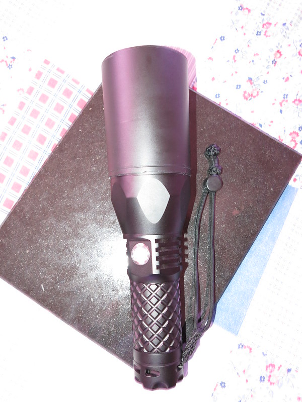
Quick and dirty, not finished, no finesse shot of the light with hood…
I think you will perceive increased throw, but only because the shield will reduce the amount of light on stuff between you and the target, making the target seem like there's more light hitting it. A light meter at the target would very likely read exactly the same with & without.