How to read 10A, 15A, 20A and beyond with a cheap meter
08/15/2015
I added an addendum to the bottom of this post with detailed instructions on how to build the shunt resistor. And here is a link to my post #28 in this thread that I hope explains things more clearly
.
.
Up until recently, I have never had to measure very high levels of current. Any measuring I have done were for single emitter lights that had current draws of no more than 5A. For that, I had used a DMM set to the 10A scale with better than stock leads. Although that was a OK for those purposes, I came to realize that it was NOT OK for the much higher current levels of multi emitter lights where the emitters are wired in parallel.
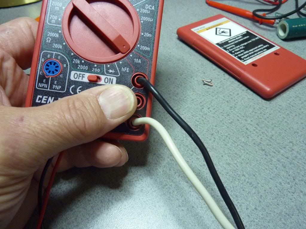
What I tried next was soldering 14 gauge wire directly to the banana jacks inside of the meter like this:
While that was better, it still wasn’t good enough.
The problem with measuring high current levels up until now, is that ALL of the current going to the LEDs has to pass down the test leads into the meter and back out before it reaches the LEDs. All of the resistance in this path can significantly alter (lower) the amount of current that will flow through the emitters. This is especially true for multi emitter lights in parallel. A very significant amount of current will be required. A lot of us here have dealt with the issues of preparing a good electrical path for that current. What I will attempt to do is provide a good method to measure that current without significantly increasing the resistance in that path. Actually there will be LESS resistance than other very expensive meters.
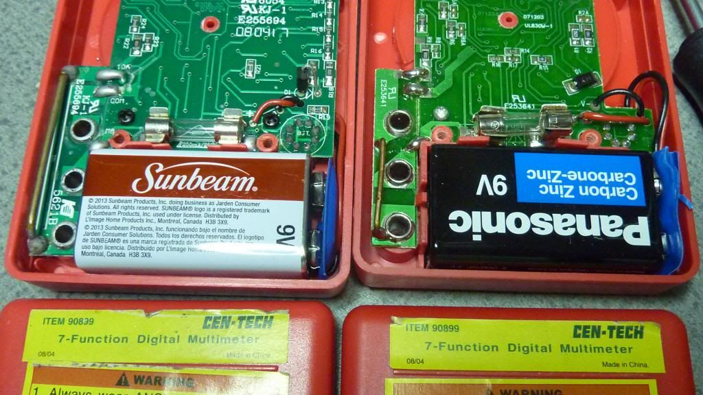
What I am going to use here is a couple of cheap Harbor Freight meters.
These meters, and many others, measure current by passing the current through a shunt resistor, and measuring the voltage drop across that resistance. The actual voltage drop is displayed as the measurement of the current. In the case of the HF meter, on the 10A scale, this shunt resistor is 0.01 ohms. This .01 ohm resistor is actually quite low for a cheap meter.
If 700 mA passes through that shunt, then the voltage drop will be according to Ohms Law, I x R, or .7A x .01 Ohm = .007V or 7mV The reading that is displayed is actually a measurement of that voltage drop. Of course when attempting to measure high currents, it is a good idea to use high quality leads to reduce any additional resistance to the path. An even better idea is to solder heavy gauge wire directly to the banana jacks to also eliminate any contact resistance. Hence the use of cheap HF meters. You wouldn’t want to do this with your Fluke 87V.
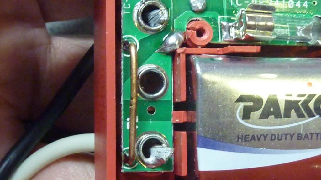
The heavier 14 gauge leads are soldered directly to the inside of the banana jack on the top hole and the bottom hole. I was careful NOT to disturb any of the soldering in the vicinity of the shunt resistor as it has been calibrated. Any additional solder on the shunt wire itself would change its resistance and throw it off. BTW, I consider the design of this meter to be quite good in this area. Notice that the jacks are soldered directly to the circuit board all around the perimeter of the jack and that there is a very short path to the shunt resistor. This would enable this meter to measure 10A without any problems so long as 14 gauge wire is soldered directly to the jack as I have. In fact, I am tempted to say that it could possible handle more. For how long I don’t know, but 20A passing through a .01 ohm resistor will generate only 4 watts of heat. It might be possible, I don’t have a 20A source to test it out on.
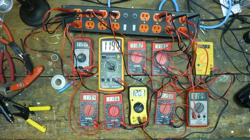
Here is that meter measuring 15A into a 6 - XM-L2 SRK with those leads. Even though the scale on the dial says 10A, the meter will read up to 20A
Even with this improvement, there is still a problem for us in reading current levels of our flashlights. There is still too much resistance. As many of us know, resistance kills performance concerning these lights. Additionally, LEDs are non linear, meaning that small increases in operating voltage will increase the current disproportionately. In other words, small increases in voltage lead to large increases in current. We want as little resistance as possible in the measuring path. So what I am saying is that if there is resistance in the path measuring the current, we will perhaps not be measuring the true amount of current flowing to the LEDs. It is quite possible that the light put together is drawing more current than what we are able to measure because there is more resistance in the measuring path than there is in the actual light. After I did the 14 gauge mod, I realized that the 2 leads wire actually had twice the resistance of the shunt resistor!
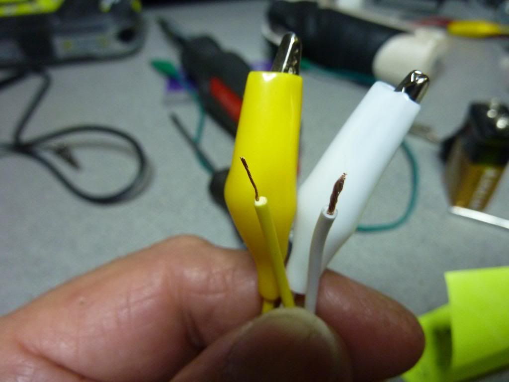
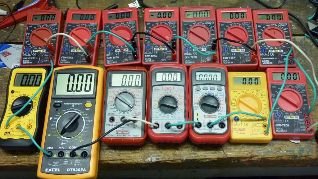
In an effort to reduce the resistance of our measuring equipment, I had to first verify that what I said earlier about measuring the voltage drop across the shunt resistor is true. So what I did was solder a couple of cheap HF alligator clips across the inside of the banana jacks. I did this so I could use a second meter to measure the actual voltage drop and compare it to what the meter was telling me what the current draw was. Here is a pic of that connection.
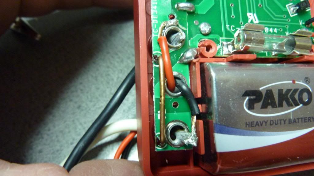
Once again, I stayed away from the shunt resistor so as not to affect it.
As they appear from the front of the meter.
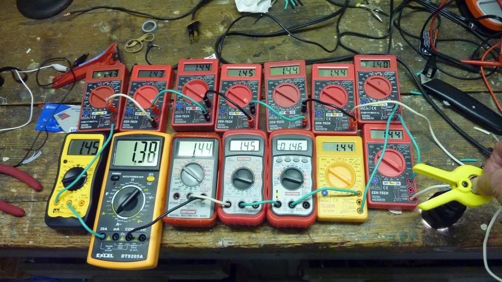
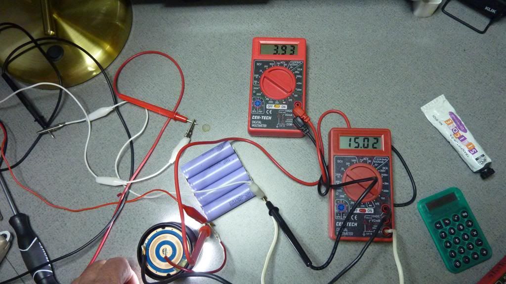
The test circuit.
What we have here is a wimpy, vintage Knight brand power supply connected to a 2.2 ohm power resistor. The meter on the left is set to the 10A scale and is measuring the current flowing from the PS, through the meter and through the resistor. The meter on the right is connected to the 2 alligator leads that I soldered across the shunt resistor of the meter on the left. It is set to the 200mV scale and is reading 7.3mV as that is the voltage drop across the shunt. Just as expected.
Looking at that picture, I found it hard to believe that there was twice as much resistance in those 2 14 gauge leads as there was internally in the meter. I looked it up and 14 gauge copper wire has a resistance of 0.002525 ohms per foot.
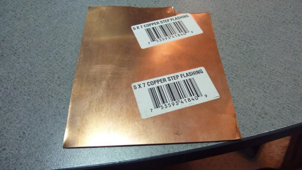
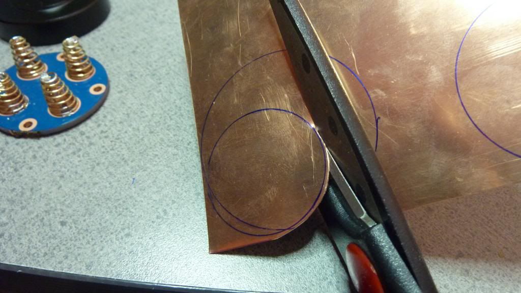
When measuring current, it’s a shame that the shunt resistor is in the meter. Wouldn’t it be a great idea to have the shunt resistor at the point of measurement and measure the voltage drop there. No need for the current to enter the meter at all. That way we can eliminate the resistance of the leads altogether. While we are at it, lets reduce the shunt resistor from 0.01 ohm to 0.001 ohm. So that is what I did. From the resistance chart, it works out that 4.75 inches of 14 gauge is about .001 ohm. So I cut off a 5 inch length of wire and soldered leads a little greater that 4.75 inches apart. I calibrated it with another HF meter on the 10A scale. At first it read a little high as it was a little too long, but I reduced the resistance slightly by allowing solder to wick into the wire until is was exact.
Here is the shunt resistor soldered to a jig to measure current of a SRK.
The final result, ALL of the current is flowing through the short white wire. The meter is measuring the voltage drop across that wire, a space of about 4.75 inches. There is only 0.001 ohms in that path.
08/15/2015
Addendum:
To fine tune or calibrate the shunt resistor, we need to make adjustments to the resistance.
While a known amount of current is flowing through the shunt wire, and the leads are hooked up to a volt meter we will use the meter reading to make the following adjustments to the shunt wire.
1 Coarse adjustment: Cut the wire a little long and solder the leads a little farther apart than .001 ohm. So we start off a little high. The reason to be a little high is because the next adjustment is perfect for lowering it a little.
2. Medium adjustment: Let solder wick into the stranded wire to reduce resistance a little. Add solder until is a little too low. The reason to be a little low at this point is because the next adjustment is perfect for raising it just a tiny bit.
3. Fine adjustment: Use a pair of diagonal cutters and gently squeeze a notch in the wire where the solder is. With a little patience, just the right number of notches can be created to zero in on an exact reading.
Done.