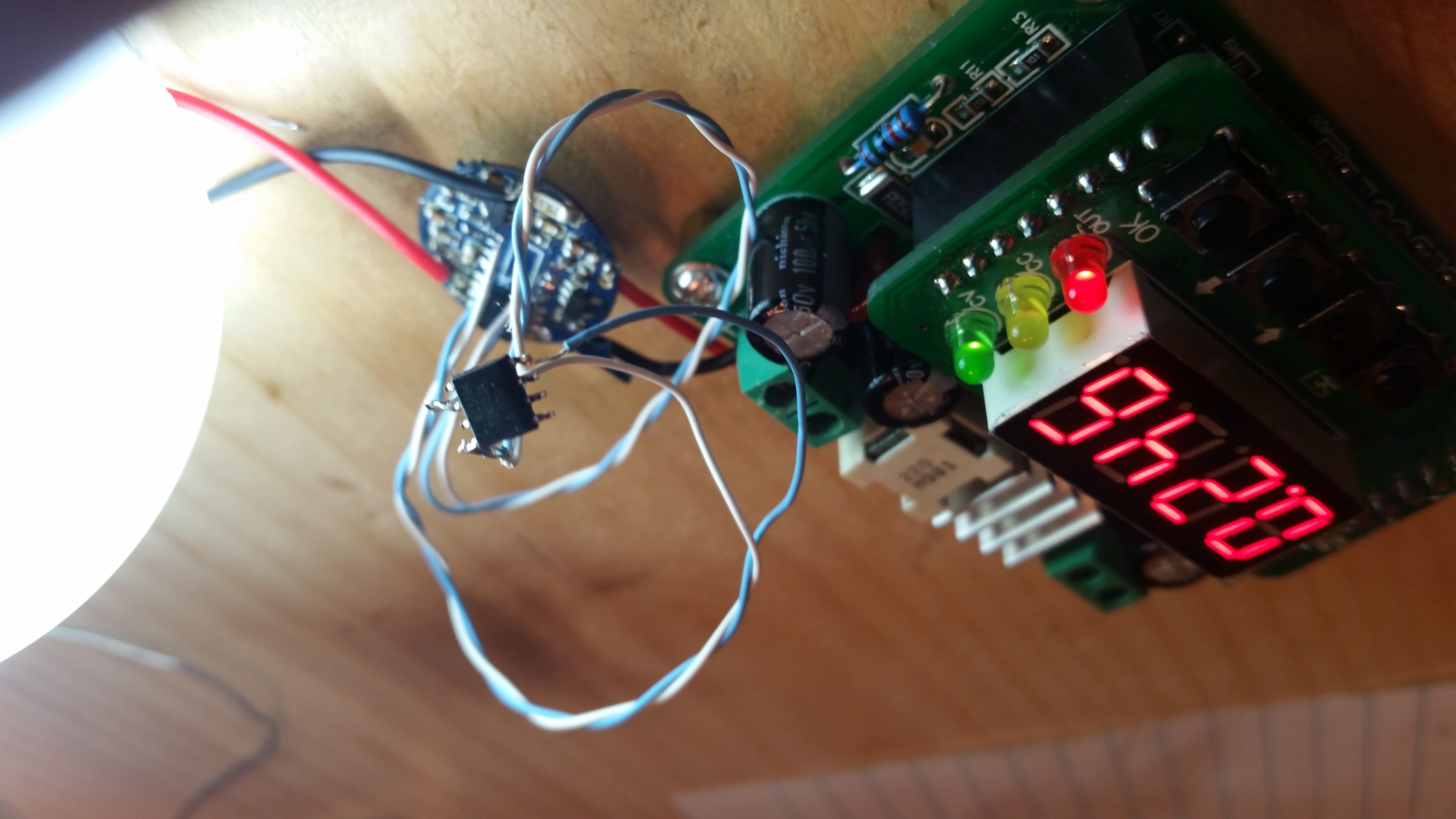
I have flashed a 150hz STAR firmware w/ ontime memory and no LVP onto an ATiny13A and successfully operated the driver.
Clearly the PWM is no good. I will increase the frequency and see what happens - later.
In another thread (post #58) I posted an ‘adapter’ for placing an ATtiny13A where a PIC12F683 goes. The link in post #58 is an update to the seriously dumb mistake I made in the one from post #47/#50. It is still untested, but I have a few on the way. As I mention over there, it requires a little filing to get working. The PCB is 1.6mm thick, so it won’t really increase the size of the driver much and should really clean up the install.
Have you checked the “regulated voltage” input with different voltages?
If it is not absolutely the same on all voltages especially on low voltage it would be better to replace just the resistors for voltage monitoring…
A small driver board is ideal to do this kind of work, the tiny10 has everything needed. If the voltage gets hooked up directly with a wire the diode might not be necessary.
B.T.W
so without an MCU, this driver can work with a momentary switch connected between pin 3 to vcc and pin8 to vcc ?
I mean while pressed: light is on, otherwise: light is off.
I thought about another thing.
I believe that the components are not meant to work in higher currents.
What if we change the Inductor and the Diode to something more quality for example IHLP2525CZER4R7M01 and SBRT15U50SP5-13
I haven’t looked into replacing the components on the LD29. I haven’t measured but I think the LD29 can produce 4A at least without dying. I do not know the efficiency at high drive currents. As you know I’ve been more interested in assembling a driver from parts than modding other drivers. Even though that hasn’t been working out so well
What I would do is strap Pin 5 (PWM) directly to VCC. Then I’d switch Pin 3 (Enable). [unless that didn’t work. Then i’d do it the other way around ] Remember that this gives you no low voltage protection or anything else that the MCU would normally provide.
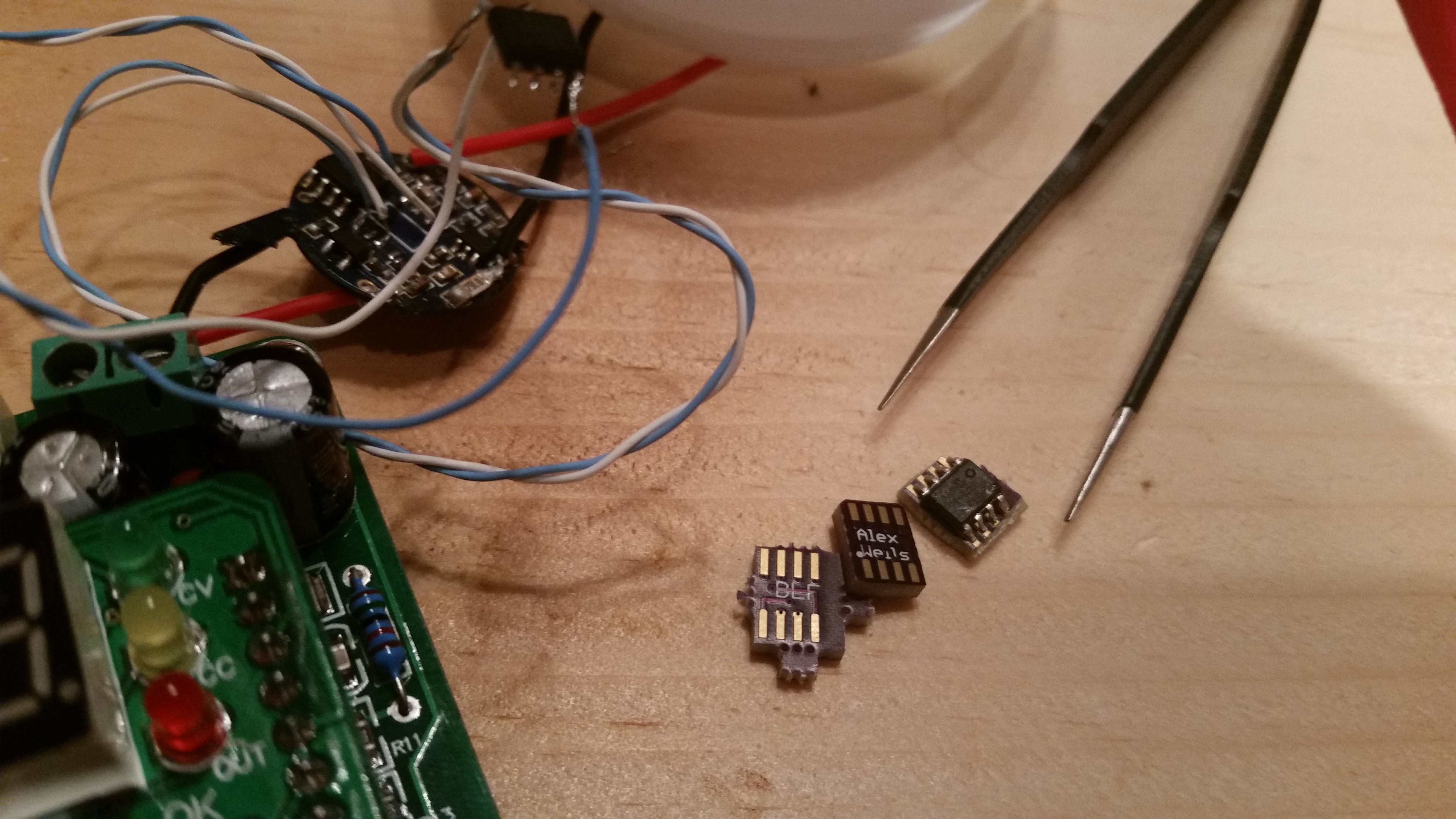
A tiny10 still takes up a lot of space and requires many air-wires in order to splice it into the stock driver (Vcc, GND, PWM, BAT+). An LD29 driver already wastes a fair amount of space since it must be installed with a contact board. See below for a picture of the first generation adapter boards. They do not work, I became confused when laying them out. I have already ordered replacements. These boards should just reflow in place of the stock PIC and lift the ATtiny up by that much. The whole assembly should remain shorter than the height of the inductor.
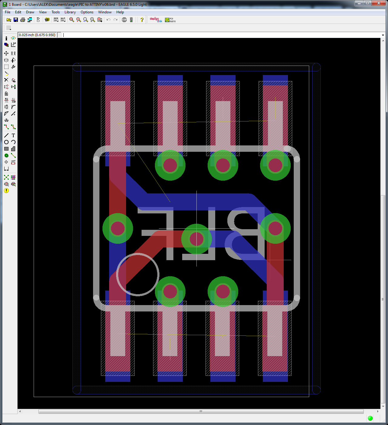
EDIT: Here is an Eagle screenshot showing both sides of the board. The ATtiny is on the red (top) layer, the bottom layer sits on the driver board. Pin 1 is marked with an empty white circle.
B.T.W
so without an MCU, this driver can work with a momentary switch connected between pin 3 to vcc and pin8 to vcc ?
I mean while pressed: light is on, otherwise: light is off.
OH MAN! I so like where you are going with that. I've always missed being able to do manual pulsing (e.g. Morse code, etc). I'm gonna add another momentary to my current mod for that. Thank you!
No problem It might be a nice project!
you may also use a reed switch instead of a clicky switch, it might be cooler - that’s what I plan to play with.
I have ordered some more components and LD-29.
I’ll try to make a nice mod when I receive it. H)