Have you guys tried Dirty PCBs ? You have to wait for shipping from China but $14 for ten 5cm x 5cm boards is dirt cheap. I tried to upload an OSHPark design to their site but they must need a different format. Complains about a lack of a drill file.
It was on the brd I downloaded but not in my .lbr directory, I wanted to copy from that stacked one that ones mine, so I could replace the single one on my board with a double stacked one…this way the board could like wight said it could be less than 1/2 the size it is now
Wait time from OSHPark is bad enough, and they are made here CONUS…I just like the purple board goodness
However it might help to get the SRK boards made in 2mm vs 1.6mm (the OSHPark boards are thinner than stock boards and sometimes lead to issues with continuity between the driver and battery tube [aw crap…they charge and extra $20 for the 2.0mm upgrade…fooey])
I wonder if those triple and 7*XML Scaru boards would do better on .6mm thick boards heat wise…hmmm
I wonder how many BLF15.17DD would fit on a 5x5cm panelized board…hmmm
Thanks for the heads up! I will try them. I’ll continue to need OSHPark for my rapid prototyping needs, regardless of how many filthy little PCBs I get shipped from China.
Also, I figure they’ll probably have similar routing restrictions to other things like Seeed: you can’t break-route panelize w/in your 5x5cm boards. If that’s the case it’s a horrible deal for small round PCBs and a good deal for larger ones or ones that you can cut apart yourself (rectangular boards).
I’m sitting here looking at an Anker USB 3.0 7-Port Hub with Charging Ports (5V / 2.1A and 5V / 1.5A). This is $30 at Amazon. What were you looking to charge with yours with that high current bad boy?
I have dual port 12V, 2 amp cig chargers for the truck for iPhones, SLR 1amp and for Xtar 500ma.
I was looking for a way to have the device auto range and draw max amps and use a cheapo ATX powersupply, make it scalable, and say hey “I did that”
Pretty much you can take a cheap’o whatever, and solder a 100ohm resistor (or even short) the D+ and D- and it will automatically pull up to 1A, but if it can pull 2A (10 watts) why not have it do it automatically
Beautiful thing…with an ATX powersupply, 5vdc is the rail is where the most “available” current is at, but it also has a 12vdc rail, and a 3.3vdc rail, the 12vdc rail I can plug into my Nitecore I4 and possibly reduce the heat generated internally due to the transformer changing AC to DC to run the charge portion, and HKJ even reviewed a NiCD/NiMH charger that uses 3vdc wall wart…well if I had one of those I could then tie into that rail…it allows a throw away power supply to be used for quite a few other things…and they usually do have very good regulation (as long as you have a load resistor on the rails [in most cases])
It all boils down to…I’m a tinkerer, and I just wanted to see if I could do it and fiddle futz around a bit (this is my hobby after all )
I think I might order me a set of the trapezoidal ones and see if it works out…use the charge doctor to see what kind of current different devices can pull
With the cost of the board down, I should be able to build a single dual unit for pretty cheap…
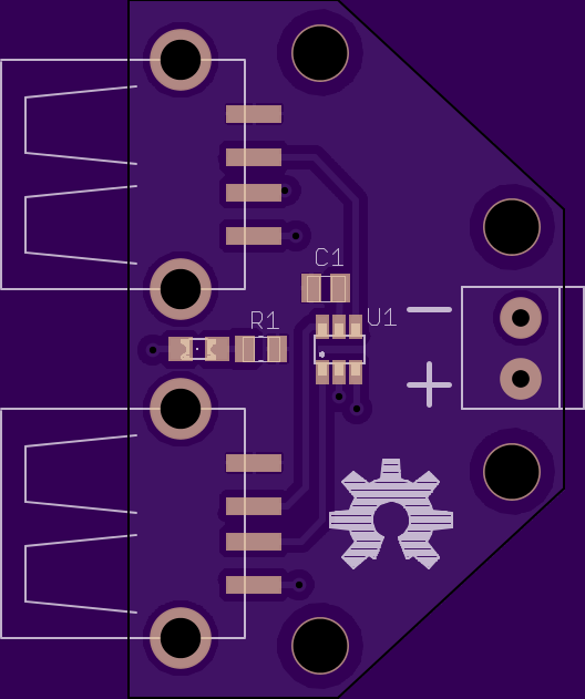
OK…render of the gerbers with updates, I added drills to allow for spacers to stack the boards if wanted (use motherboard standoffs, drill holes directly into the housing of the powersupply, stack 3 boards high, voila), moved the LED between the USB ports to cut down on the glare (we all know those little LED’s can be pretty bright)
This board really isn’t the best, but maybe it will give you some ideas. I noticed that you did not place any components on the bottom, so I didn’t either. My first instinct is definitely to move all the 0805’s and the SOT23-6 onto the bottom. Instead I cleaned up that stray trace so that the bottom is 100% GND. I also connected the shield on the USB ports to GND. I had to move the power LED so I added a second set of pads for that - populate 1 or both sets. Since you seemed hot on the idea of >2 ports, I added a placement for a second set of terminals (for pass through / daisychain). The terminal housings do sit on top of other stuff (SMD pins). Screwholes are M3, so FDD/ODD screws rather than MBD screws. When slimmed down this far the board costs $3.65 for three. I’d say the sweet spot is probably more like $4.50 with a little more space given to everything (mounting considerations, no stacking of headers over SMD pins, etc). Also, I trusted your understanding of the pinout for the chip. I didn’t check the datasheet or anything. Note that I swapped the ports, it was easier to route that way. The corners may be flimsy, but nobody cares if they break off as long as you are using all 3 mounting holes.
I agree. I can’t help wanting to smash the PCB outline as far in as I can get it though ;-).
Even a 2-port stack with all through-hole components and using all Chinese eBay/Aliexpress parts seems like it ends up awfully expensive (and awfully bulky once you strap that ATX PSU onto it).
OTOH you know a good-brand ATX PSU has clean 5v as long as you put a big (wasteful!) load on the 12v to avoid cross-loading (unless it’s a new PSU w/ 5v regulated from 12v… why are you wasting an expensive PSU on charging USB devices though?). And you know what chips you put on the charging PCB. So squeaky clean charging is maybe worth something…
Nice! I put those eurostyle blocks on mine for tying in the powersupply leads, your design could probably benefit from a smaller form factor maybe even header pins