Ok, we are now past 150 posts in this mod thread. Time to do some modding? :D
But first.
K50 vs TK61 reflector size. I think its easy to see the size difference in width here due to the AR coating and light.
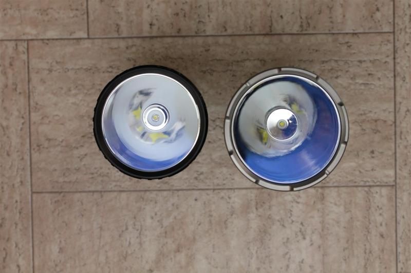
K50 can fit the large XP-G/XP-L from IOS.. Im fairly sure you will avoid the reflector if you keep the soldering near the edge of the mcpcb.
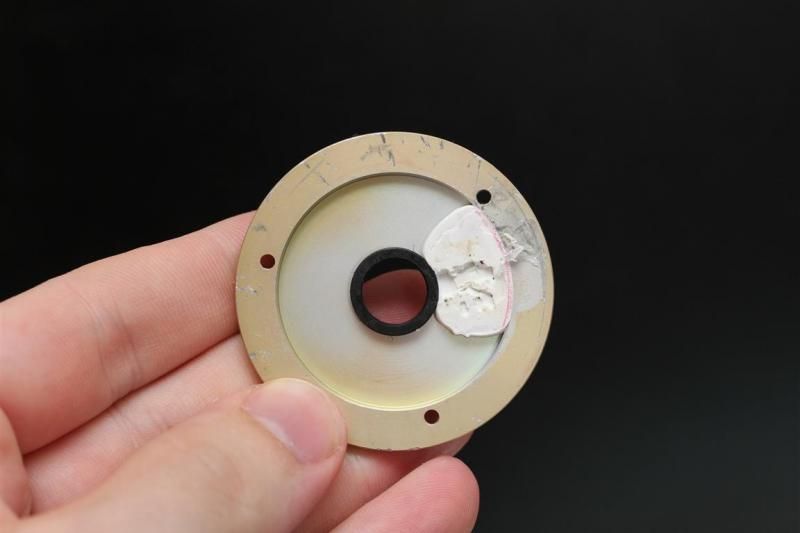
Ok, the mod... No last part of teardown first.. :p
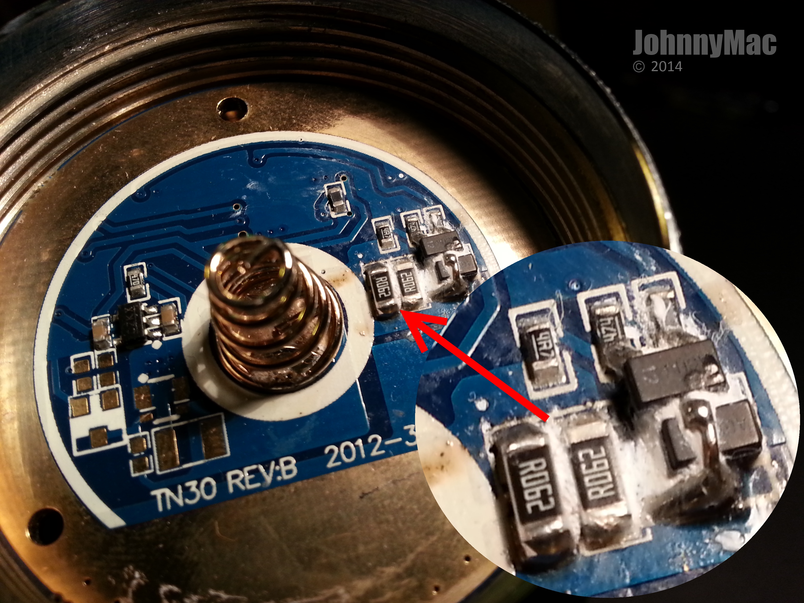
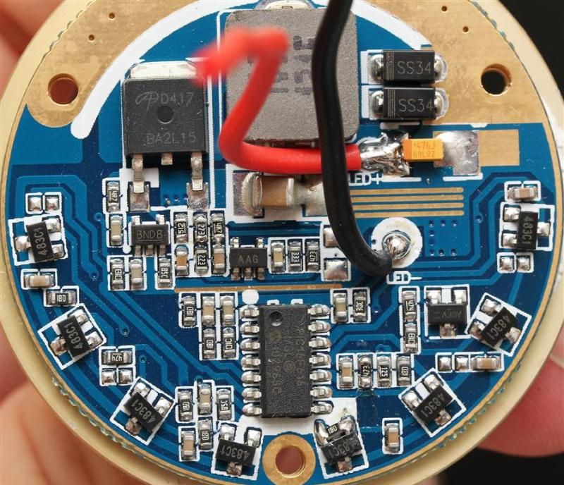
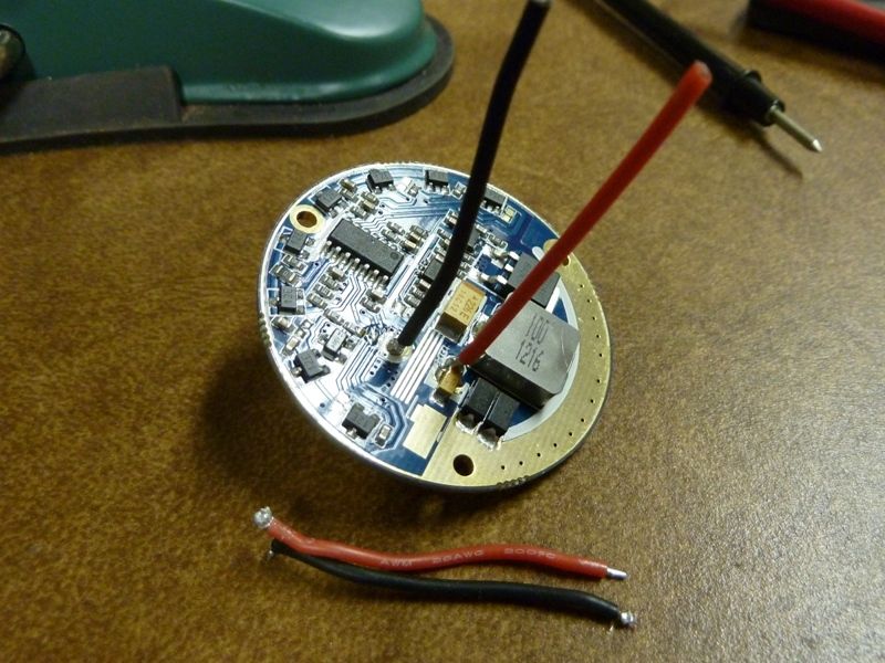
Driver was really stuck to the ring it was attached too. As you can see from the scratches. I started working my way under the driver with small flat screwdrivers from the opposite side of where the silicone stuff was. Once I was around to the area where the silicone stuff was, I used a knife to cut it away. Not too far in though. Then I put more pressure on the driver from different angels, and the spring, and it popped off with a loud sound. I did not like this process, required a good amount of force. I was afraid of breaking the driver or some components.
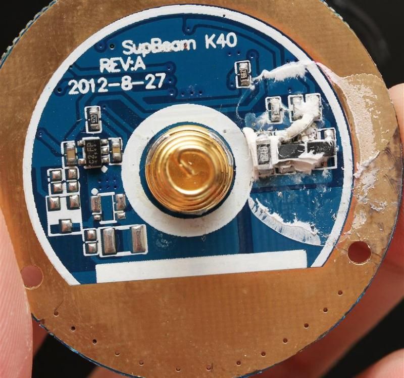
Some numbers may be off, and not that precise due to the behavior of the driver and me going a little bit by memory.
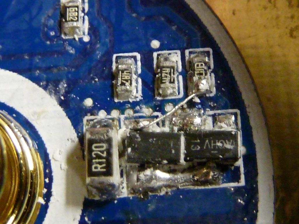
The three stock sense resistor that are stacked are R100, R120 and R120 (0,0375 total). Ideally, you do not want to have more then three in height. Because it becomes too tall. Stock setup gave around 5A at startup to the emitter at startup, and sinking a little before the power decrease.
Adding one R100 to the stock setup gave roughly 6A (0,0272 total)
Adding another R100 to the previous setup gave me roughly 7A (0,021 total)
Starting over with a combination of R100+R030+R100 gave me around 7,9A at startup. (0,0187 total)
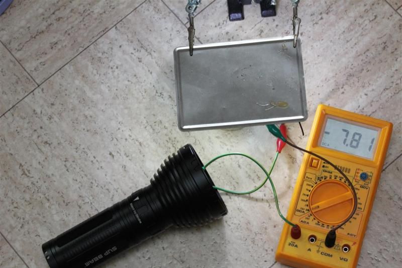
I mostly did my testing with two different power supplies. But at this point moved over to using the flashlight and batteries.
I had tested the 7,9A (startup) with 3 XM-Ls in parallel. I then moved on to test it with an XM-L2 on Noctigon. All seemed well.
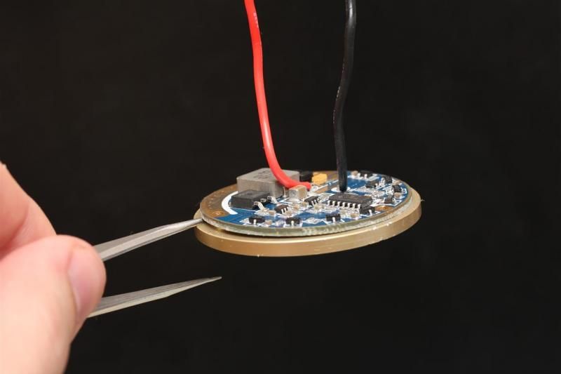
Put the driver into the light. I then did spring mod (should not matter, I used a PS before). And upgraded to 18AWG wires. Hoping to see the same result as with the Noctigon and the powersupply.
Fired it up with the stock emitter. Instant poff. Hmm. Could the wire increase have affected it? I don't know..
Tested it with the 3 XM-Ls in parallel, and it started on the same 7,9A and sank like the titanic like it usually did. I think the instantly killed emitter was a bit strange. But I was probably at the very edge when testing it before to an XM-L2 before I tested it in the light.
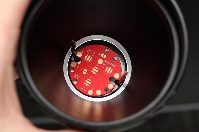
I removed one R100. (Using R100+R030 for a 0,023 total) Also reflowed a junk XM-L2 on to the stock mcpcb for testing. Verified that the stock K40 mcpcb does have direct thermal path.
That resistor combo gave me around 6,6A to the emitter. Same sinking pattern.. I also saw that it jumped down to 5,6 after some time.. I was worried about the behavior in general. (I had forgotten that it cuts down a bit on power a little after a minute).
I decided on a really conservative setup.
R100+R100+R100 (0,0333 total) and changed emitter once more, this time to a keeper, XM-L2 U2 2C. I was done with the high amps testing.
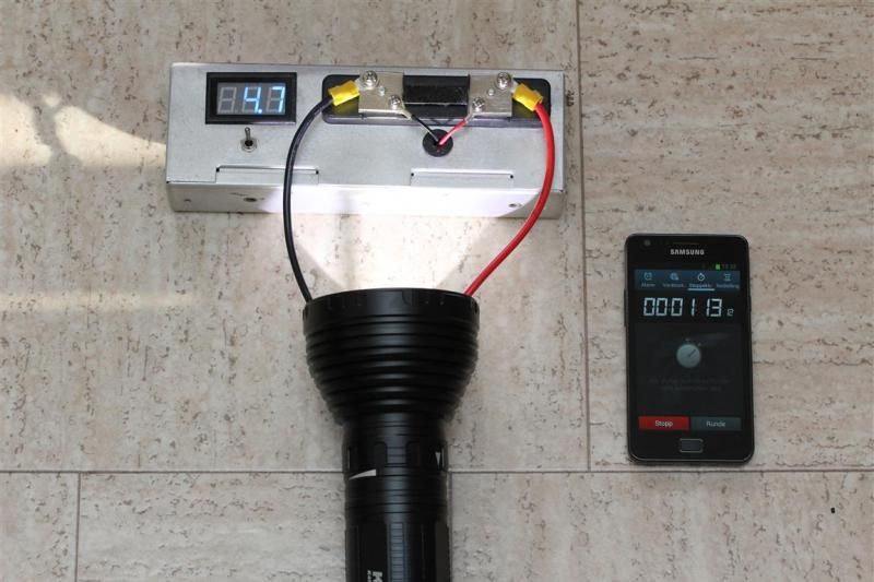
Startup current at 5,4-5,5. But like always, it sinks quickly. Settled around 5,1-5,2 before the power decrease.
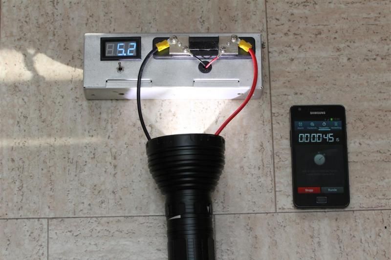
After power decrease.
One day later. Nah. That was just too boring and low.. :D .. I know its capable of more..
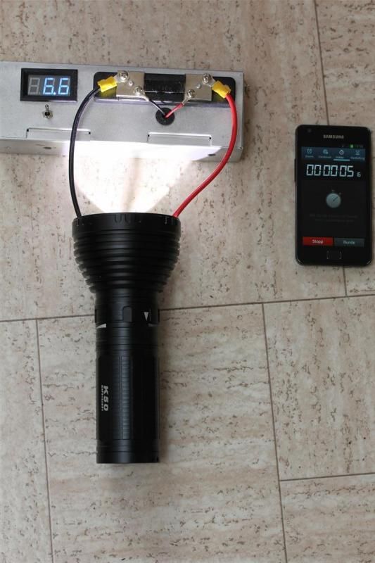
Latest setup. R100+R030. Yes, that setup again. I considered to push it further, but decided to not bother due to the limited gain after some use, and the higher risk.
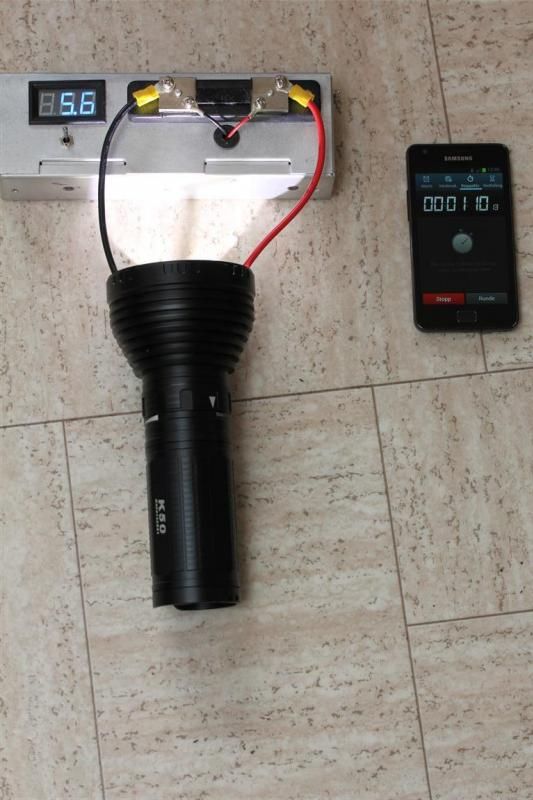
Once again, ill show you guys the behavior. Started at 6,9A. Drops like the titanic (check out the clock on the cell phone and the amps). Down 0,3 Amps in 5 seconds.
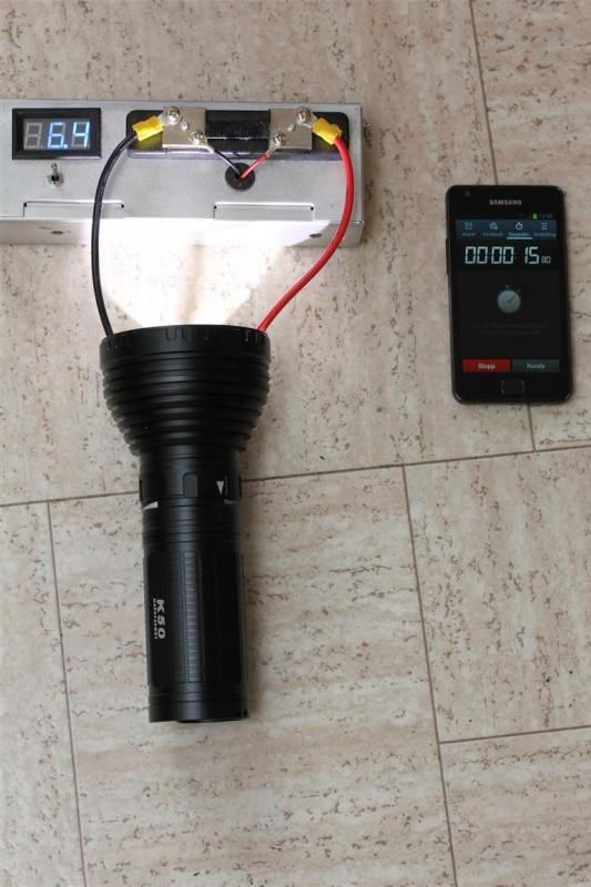
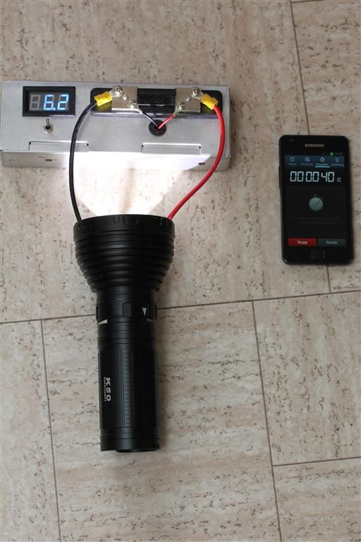
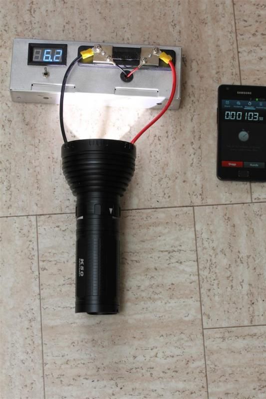
Then comes the power cut a little after a minute..
I decided to leave leave it like that. I had put already put fujick on the resistor and let it dry. I considered it done now.
Summary of behavior:
This driver can easily do 8A, at startup, but it sinks like a rock. Due to its behavior it maybe have considerably more than 8A the first milliseconds at startup, and that is not healthy.
This means that if you want at least 7A (before the power decrease that happens a little after a minute), you really have to aim for 8A. Aiming for 8A is not healthy. Maybe it can do 7,5A peak at startup and work nicely and reliable. But its likely to loose close to 1 amp of power the first minute and then being reduced more when the power decrease kicks in. And the further its pushed, the more power decrease you will see too.
All this behavior means that the light is capable of giving some nice bragging numbers at startup, and at 30 seconds if you push the emitter close to what is healthy. Startup numbers mean nothing to me if power is considerably lower after 1 minute and 15 seconds. Its really not what I am expecting from a supposedly properly regulated light. And that is the thing, the further you push it, the more output you will loose in a short time, and push it too far.. Either poff, or risk decreased emitter life.
Due to that behavior, I decided to not push mine that far. Then again, all I did was playing with the resistors. Ill leave it up to others too see if any special tweaks can be done to improve the driver.
Testing the modded light.
kcd at about 30 sec: 206
Lumen: 1638 (1722 at startup)
I did some heat tests too. Ran the light for 20 minutes. After the amps have stabilized, and the power decrease have been done. I was looking at around 5,6A to the emitter and 1533 lumen.
From the point where the light have done the power decrease I checked output 10 minutes later, it had dropped less than 70 lumen. This basically means that the stock heat sink is working. When that is said. The heat is mostly around the magnetic ring. The fins on the head does not become that effective or hot compared to the magnetic ring. No surprise really.
Id say there is little point in spending time improving the heatsinking on this light. The majority of the output sag in the beginning is output sag due to how the driver works, not due to bad thermal transfer.
Other:
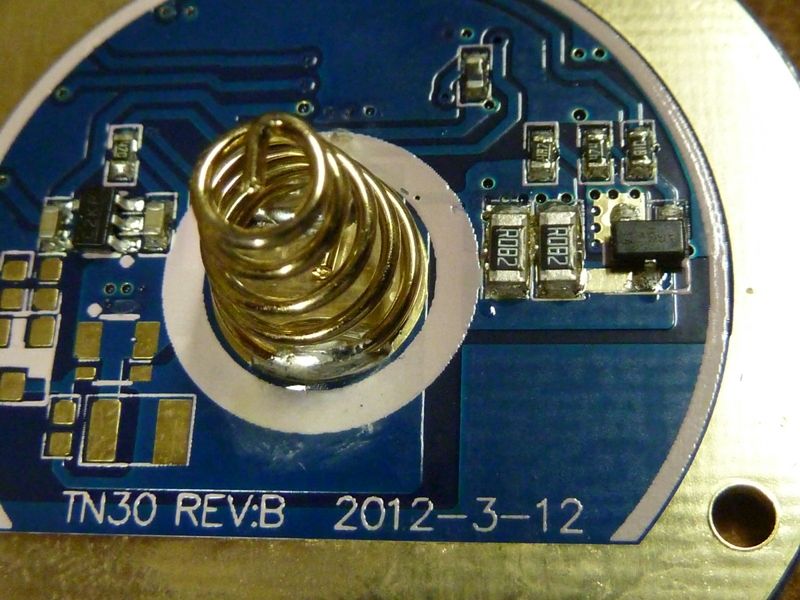
Dale, reflector is beefy aluminium. You will like the weight of it. :D
I lapped the pill on mine before doing all this. Used Artic siler 5.
I did not bother doing efficiency numbers.
I would be extremely careful when putting the reflector back in if you have a de-domed emitter in it.
Summary:
All in all, not the best light to mod the driver in based on my testing with the resistor mod. Then again, I often have too high expectations. Its already good as it is stock. When that is said. Output does sink a bit with its stock too, and then there is the power decrease. I never measured, but I would not be surprised if it was down to 4,5A at the emitter or lower after 1m 10sec when its stock.. Hopefully others can share some details too for a cross check.
Happy modding, if you still want to mod it...
Sorry about the long post..
Edit: Corrected some lumen numbers, and removed some info about the U2 2C.
 ).
).