Sounds good to me. Should be able to do both lights with only OSH Park order then.
wight wrote:
Based on hideehoo’s info above, I’m thinking 26mm with 4 nubs to take it out to 27mm (which add no cost since they fit in the OSH Park ‘rectangle’) will be the way to go. Do you see any reason not to go that direction?
I just measured my 9xT6. The driver ledge opening is 25mm. The driver bay is 27mm. So I agree with hideehoo. That approach should work fine.
OK, sounds like a winner.
I expanded the diameter to 26mm and added 0.5mm tall nubs on the “corners.” That brings the driver out to 27mm. The process of adding the nubs has made the primary outline very slightly not-true, so depending on where you measure it you may have 26.05mm or something like that.
Since there was space I also added resist-covered pads for Pin3 (on/off output or analog input such as for temp sensor) and Pin5 (PWM output or analog input). This driver should work fine with dual-PWM firmwares where 7135’s are slaved off of Pin5 for regulated modes of any kind, including low moonlights or whatever.


Ordered a set. Thank you wight!
EDIT: Ordered the components I need from Mouser. Looking forward to trying one of these bad boys..
> a $20-$40 1500W heat gun with good results. (Milwaukee MHT3300)
Hm, closest thing Milwaukee has now looks like it costs well over $100. Sigh.
Not to worry. ![]() Milwaukee probably didn’t make the thing anyway, based on the recall notice it was manufactured by Wagner. In fact, the housing and controls of the Wagner HT3500 look identical in form/function to my Milwaukee MHT3300. http://www.homedepot.com/p/Wagner-HT3500-1500-Watt-Digital-Heat-Gun-0503040/203474822
Milwaukee probably didn’t make the thing anyway, based on the recall notice it was manufactured by Wagner. In fact, the housing and controls of the Wagner HT3500 look identical in form/function to my Milwaukee MHT3300. http://www.homedepot.com/p/Wagner-HT3500-1500-Watt-Digital-Heat-Gun-0503040/203474822
I’m definitely not saying that it’s the best way to do it, but a big heat gun is a handy tool for DIY’ers. Laminating foam, peeling adhesives, softening other materials, etc.
Already got components from DigiKey and stencils from OSHStencils, so I'm ready to go! :)
Thanks wight, nice looking layout, liking the big pads a lot! ;)
With the diode having the numbers 41 on it, and the 1 being where we would normally expect a line, does this line or 1 go to the point of the triangle?
The line goes towards the point. There should also be a line between the pad and the MCU.
I looked up the datasheet on the diode and went with it. :)
The diode is marked with a 41. The "1" goes closest to the Zener pad and towards the MCU, the "4" is closest to the R1 pad and towards the 10uF cap.
Tried to look at your picture to see how you had oriented it on yours but the image wasn't clear enough to tell.
The one in the picture is a SOD-723, which makes it harder to see since it’s so small. If I recall correctly it may not have been marked, I had to test it with my DMM to figure out the polarity. Either way you sure can’t tell from my picture. ![]()
Please check this, you might be able to tell from this picture…
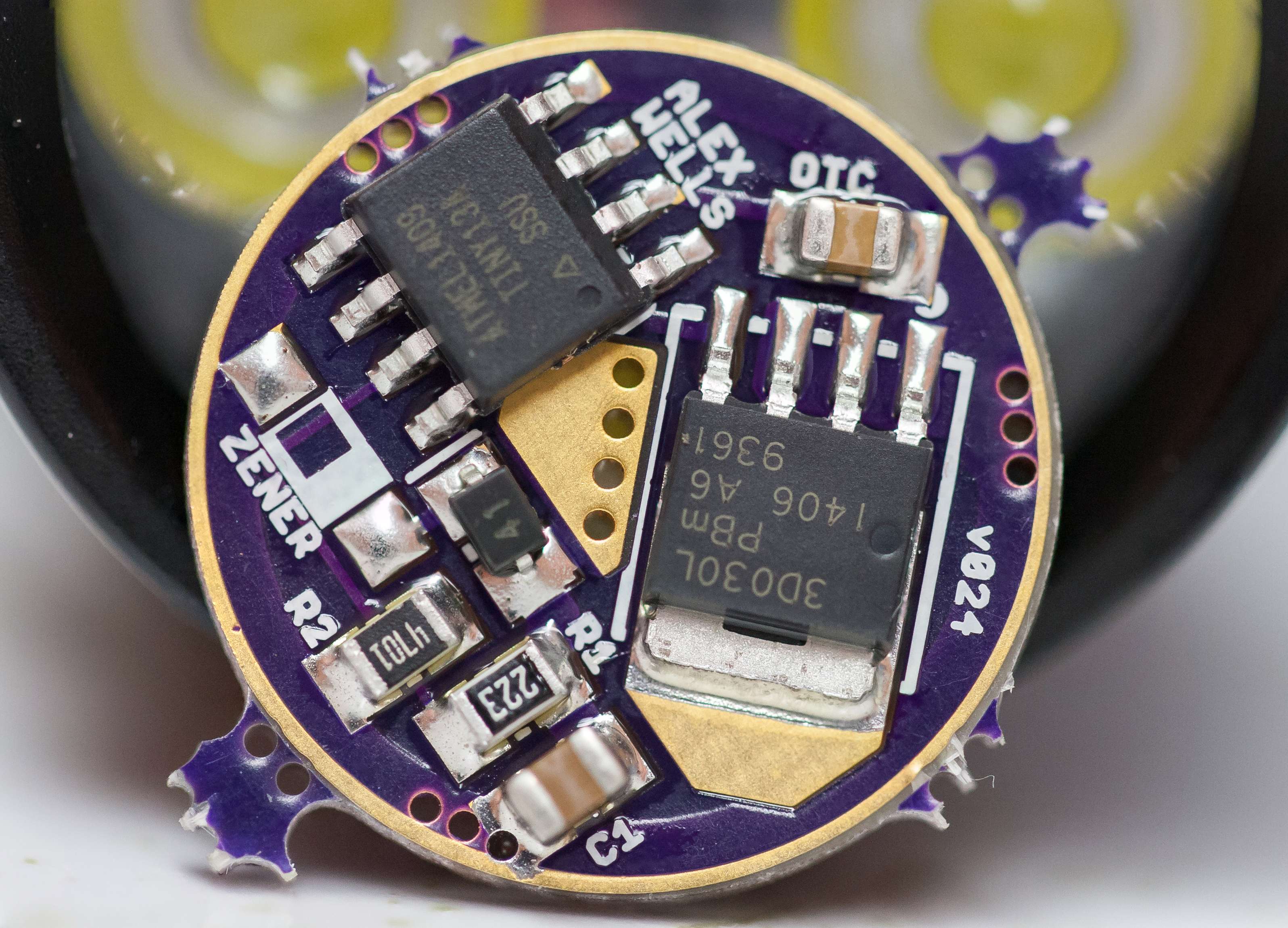
It can be clicked on for a larger view. ![]()
Caps crooked. ![]()
Edit - Dang nice work Dale.
Does that look nice Dale, i cant wait till i get my boards and parts and the best part my newer version of the 2008D
It was destiny, Kester EP256 style. ![]()
Thank you sir. I LOVE using solder paste masks from OSHStencils! ![]() I MIGHT could have done it almost that neat, but this single sided board is just so easy with the stencil…
I MIGHT could have done it almost that neat, but this single sided board is just so easy with the stencil…
Looks fine to me. Resistors and diode are placed correctly, so is the MCU. Since the caps are unmarked we must assume that they are placed correctly. Is that glare, or is there some sort of (white) flux residue around the FET’s tab?
DoF appears to be very tiny in that shot! ~2.0mm I think?
So, in this normal configuration, can that Zener pad closest to the outer ground ring be used to solder a ground lead wire to, for establishing ground inside the pill with a screw instead of worry about press fit connection or outside soldering?
That’s a stacked image. ![]()
The Zener is OK for that. For my purposes I’ve been using the outer 3 legs of the FET - this makes for a larger and sturdier connection area for your GND wire.
Crazy! I should expected as much. ![]()