if you use Nanjg 105C (D)
You can change the firmware of the microcontroller.
Use Pin6 for Turbo mode and Pin5 for Low Modes.
Use on pin5 one or more AMC7135 chips.
You can use this firmware
#define MAX_MODES 2
#ifdef REVERSE_SW //from Lo to Hi #define SetMod0() Mod0075 //Pin5 PWM 8kHz #define SetMod1() Mod0350 //Pin5 #define SetMod2() Mod2100 //Pin5+6 #define SetMod3() Mod2100 #define SetMod4() Mod2100 // Mode 5
#else //from Hi to Lo #define SetMod0() Mod2100 #define SetMod1() Mod0350 #define SetMod2() Mod0075 #define SetMod3() Mod0075 #define SetMod4() Mod0075 // Mode 5 #endif
EBay seller E-best_trade has the ph4030al mosfets listed. As the original seller has sold out, I just ordered 20, the lowest they would go on best offer was 65c each. Will report back when they arrive. mosfet
Crap, now only I see the reply. Thanks for the information, but I am not gonna flash the driver at the moment, mostly because I feel lazy to remove it from my HD2010.
Let’s say I have a poor FET with high internal resistance and it doesn’t deliver more than 3A to the emitter, can I just leave another one or two 7135 chips on the board, to sort of lower the overall resistance?
that is only true for an ideal powersource. In reality the extra current via the 7135 will cause a slight voltage drop over the driver (which in total is the good thing) which will lower the current through the FET a bit. ...or not quite like this but someway like this
Update! And a bump!!!
As the original FET seller sold out I ordered 20 from ebay seller E-best_trade Link they arrived in 8 days from Hong Kong. And test good, genuine original.
.
I decided to build a Fet+1 driver. This turned out to be really easy with just a wire link from pin 5 to FET gate.
.
.
.
I used Dr jones basic MiniDrv firmware and added a couple of lines to make it duel PWM. Sorry about the screen shot don’t have any other way of showing.
The output is low(2ma), medium (350ma), high (1.2A), turbo (4.5A), with a 20 second turbo step down and no memory always starts on low.
.
Great work Major! Love it that you got the FET+7135 option working! I'm jealous of your skills too, I will never go into the coding/flashing direction I'm afraid, and the UI you made is close to my perfect one :-)
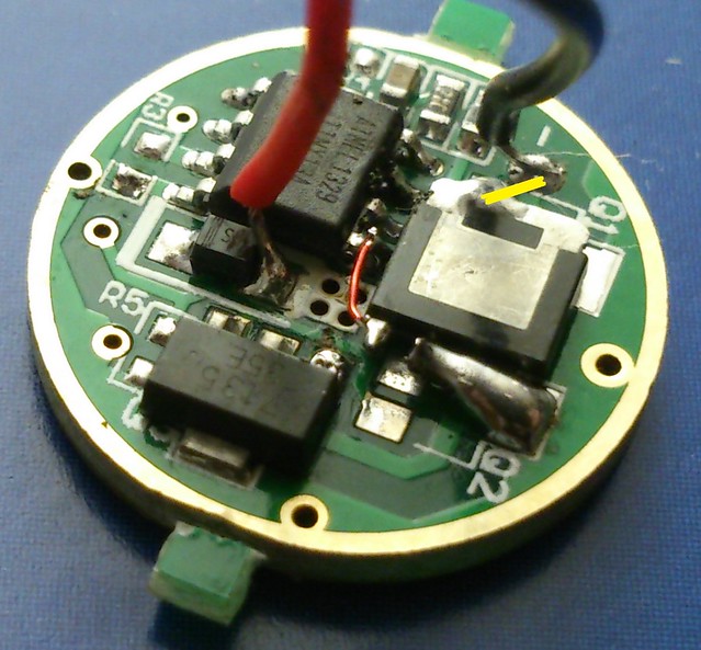
Major, for the record, I take it that the FET-drain is connected to the led-minus pad, it is not clear in your picture, I have drawn a yellow line to show it:
.Yes that line is correct, I soldered the FET-drain to the pad where the 7135 used to be.
.
.
Thanks, I’ve been looking for a cheap and easy Fet+1 driver for ages. Cheers but im no programmer I just copy what the clever people on here write and alter it until it works!