The first LED Maglite I have had to play with, gifted to me by another kind member here.
I have always wanted to see if one could use a high powered XM-L LED in one of these things and still retain something like the stock focus adjustment, with the stock reflector and center pedestal.
I guess I will play around with it some... In case some of you haven't taken apart one of these, I have a couple photos - Naturally 
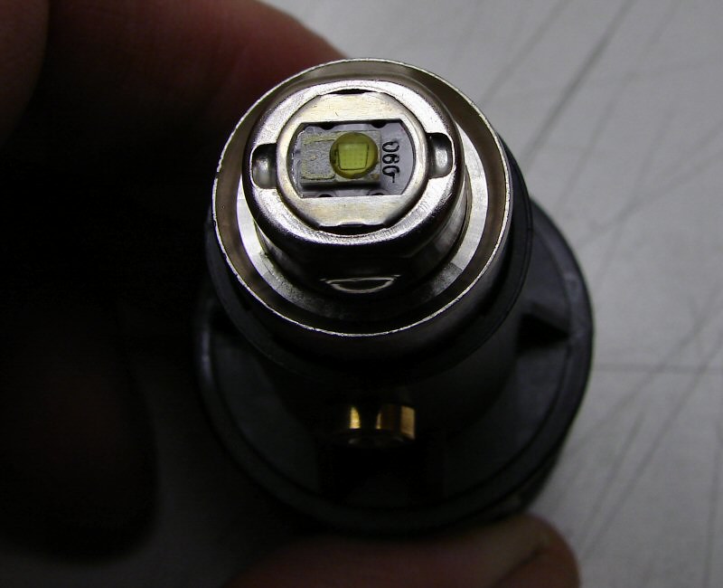
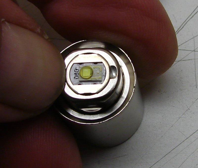
Which emitter is that? Luxeon?
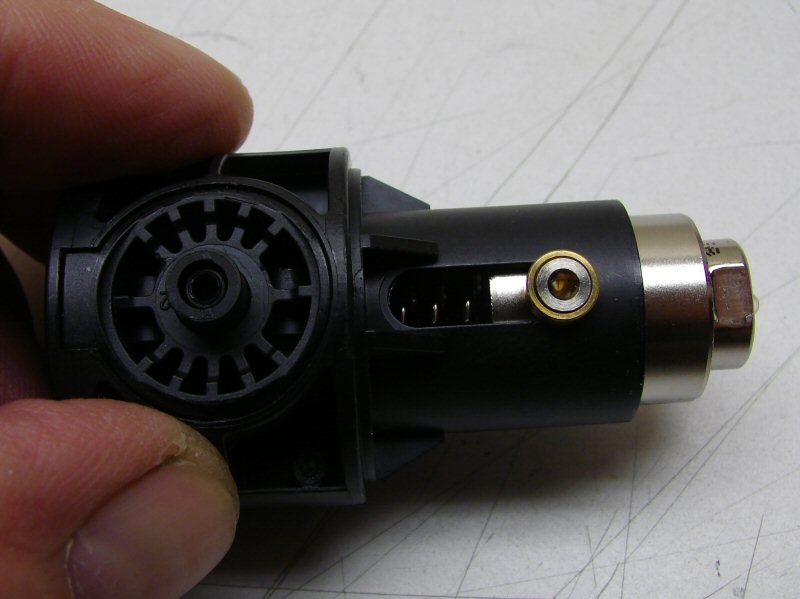
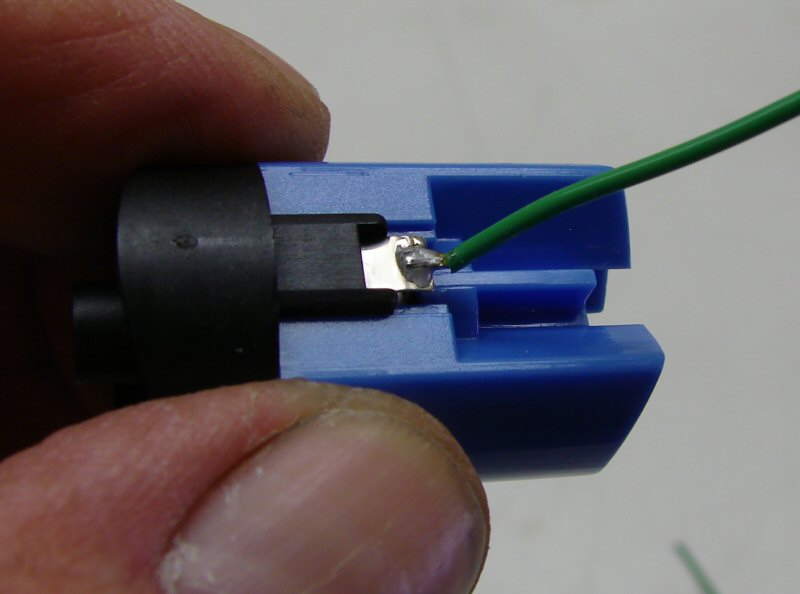
Side view
Screw removed and sub-assembly is out.
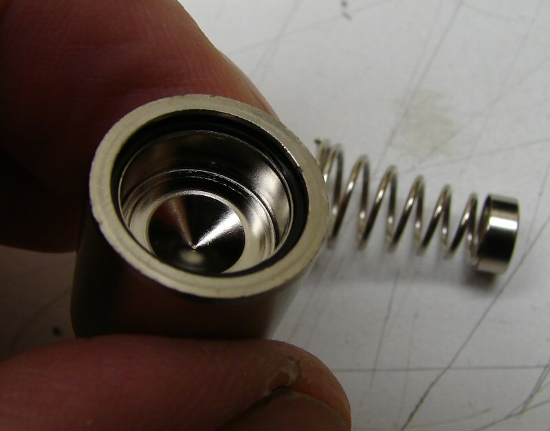
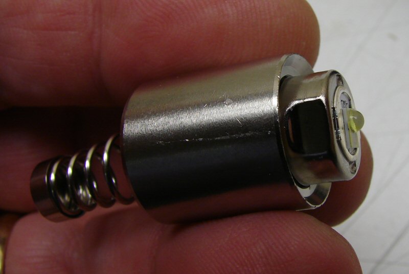
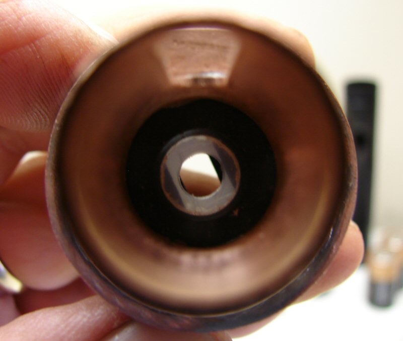
Pulled the spring off and there's a cup inside, which does not fall out.
It doesn't come out the top either, so just set it down and push on the center LED assembly, with two thumbs (only one showing here, had to use the other hand to run the camera).
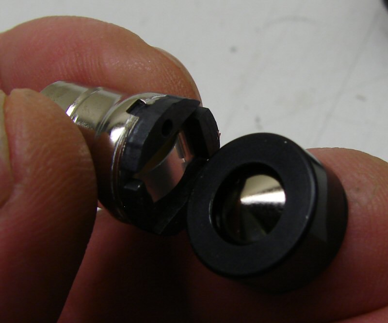
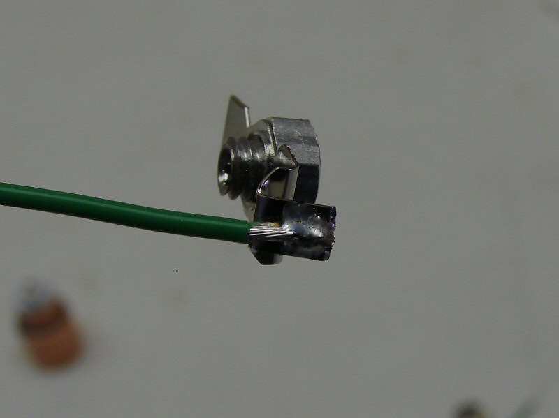
LED assembly (pill) and the spring cup.
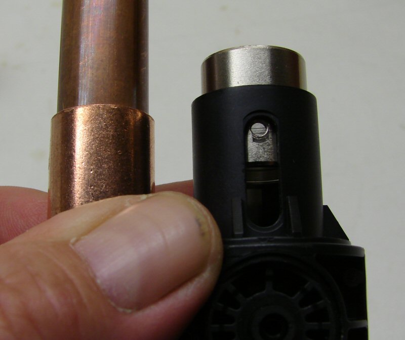
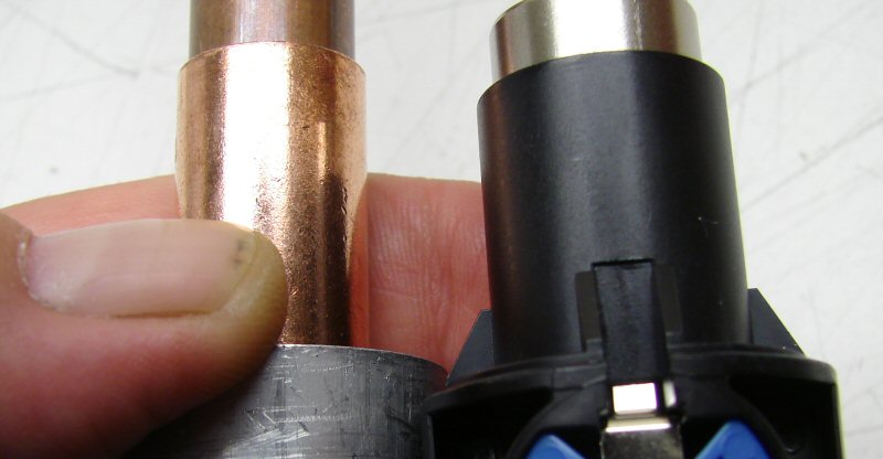
Now what can I do to replace the plastic tower? Looks like a copper coupling would be about the right diameter and a piece of copper pipe would slide into the coupling in place of that steel one over on the right. Hmmmm, it might just work. Fill that copper pipe so it's a solid "pill" and the Nichia would go on top, slot the copper coupling so it works like the plastic tower. Put the screw hole in the filled copper pipe and it will work like the original steel insert.
But I need more mass,
So, how about using a slice of Aluminum that fits in the body and attach the copper coupling to that so it has a base plate and it gives mass and it will contact the body for more heat transfer?
But, what about a driver? Fit a 7135 driver up in a hollow in the Aluminum and it sits right above the switch contact. Interestinger and interestinger...
And what about transferring heat from the copper center "pill" that moves, to the copper tower? That's an easy one, but to make it more interesting, let's use that copper "pill"/tower as the negative contact. Instead of thermal grease between the two, let's use some grease that conducts electricity.
I've got it all in my head, now I just have to do it and work out all the bugs, but you got the gist of it now. Maybe?
More to come............
----------------------------------------------------------------------------------
08-11-2012
The new tower/heat sink is partially made, so here's a photo:
I ended up using copper to make all of it. When I got to looking at it, I knew I wanted to keep dimensions as much as possible and I wanted it to be fastened to the top of the switch housing. That meant, it would have to sit against the "C" ring in the body, so I made it out of four pieces of copper, plus the coupling sticking up.
I cut a 1" copper coupling and heated it just about red hot (to soften the copper), then I flattened it and cut out three circles. I also cut out a circle (a little larger), out of 24 gauge copper sheet. I soldered them all together and used a drill and dremel to cut out the center hole, where the coupling goes in. Then I drove the coupling in and soldered it. Now it's a one piece tower and heat sink.
It's not going to be a fantastic heat sink, but it should support the Nichia led I am going to use. I still have to cut the slot in the tower and make the solid pill, as well as a lot of clean up, so there's plenty left to do.
That's all for the moment.
-----------------------------------------------------------------------------------------------------------
08-12-2012
I'm not one to say I'm proud of something, cause usually I'm not satisfied with the results enough, but there's always a first. I am proud of how this tower came out. I never thought I would be able to make it and have the tolerances come out well enough to have it work.
The tower itself is composed of a 1/2" coupling with a slot cut in it. Inside is a 1/2" pipe, filled with copper shot and solder. On top is a 3/8" copper coupling filled with copper shot and solder. The top and bottom are covered with copper sheet.
Here's how it will set on the gutted switch housing. I will use the original spring, but it will be modded for less resistance. I happened to have a 3mm tap & die and that was what I used to make a threaded hole for the stock guide screw, in the slot. It all works as it should and it is very smooth movement and no wobble.
I thought at first, that this thing was cocked a little, but I took this shot across the top and it looks like it's pretty straight and level. I really did not think it would come out this good and I'm betting I couldn't do it again if I had to.
That's all for now. I still have to dril for a wire and mount the led on top, as well as many other little things.
-------------------------------------------------------------------------------------------------
08-13-2012
Well, just to show the rest of the process, here's how the assembly went together (up to a point).
In order to keep the Positive isolated, I had to wire directly to the switch, so the spring would not be "live".
Instead of the metal cup, I put a plastic ring down there, so the wire could go thru.
I soldered the other wire to the negative terminal and fed it up thru.
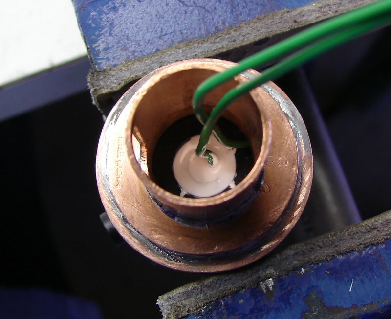
I put AA in the center to seal it and isolate it, then (no photos), I put the rest together and wiored it up.
No photos, because I didn't take any before testing and it was a FAIL. I will explain in a minute.
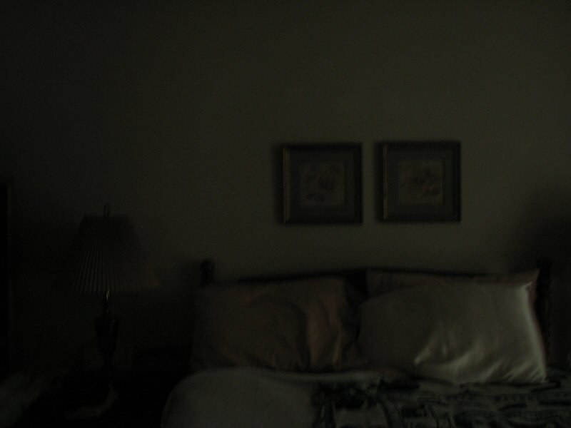
Beam shot standard, the bedroom during the day.
1 Second shutter, IOS 200, Aperture F:2.7 Daylight white balance.
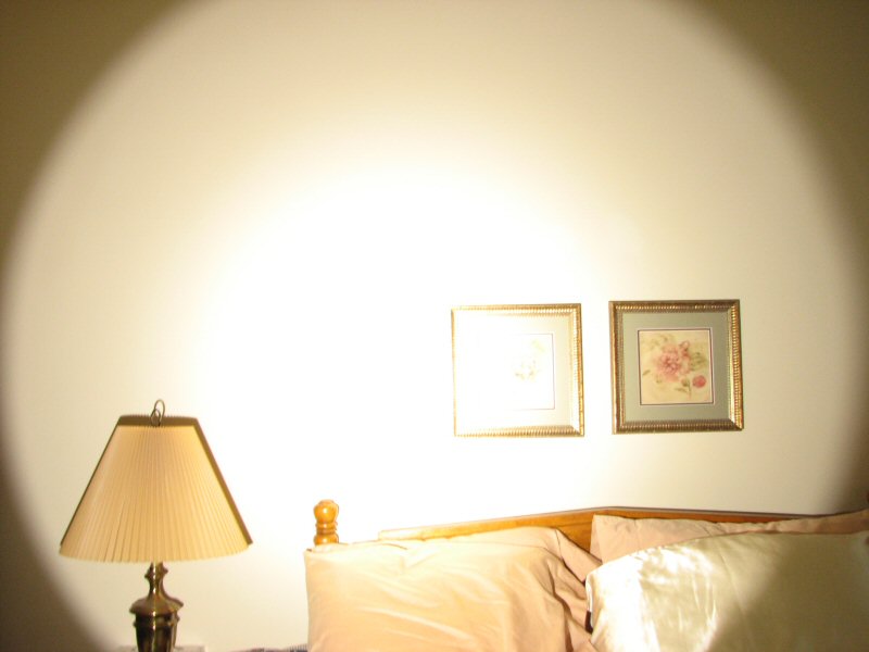
1/30 second shutter, everything else the same.
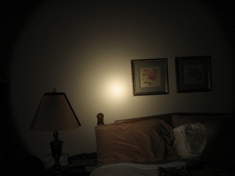
Program Mode - Shows just about what I saw color wise and a little less bright than what my eye saw. (Our walls are not white, they are some kind of "pale peach", (according to the wife). Not condusive to good beam shots.
OK, here's the SCOOP on the Poop.
I assembled everything and put it all together. It worked for a minute, I mean the turning of the head moved the led up and down, then POP! The screw that the reflector touches against came out. The copper is too soft to support the strain. That's why Maglite uses Steel. I was concerned about this. It pulled the few threads right out of the copper. OH WELL, that's how you learn, by trial and Error. I see the error of my ways now. LOL
I went ahead and put in a 3mm by 10mm long screw in the hole and threaded it in as far as it would go and that works. The head can still be rotated and the led assembly will go up and down, but because it's just a screw instead of a roller, it is stiff and something will break, sooner or later. So..... now it's a garage light, till fall comes and I can strip it down and make a 1D out of it, to sell.
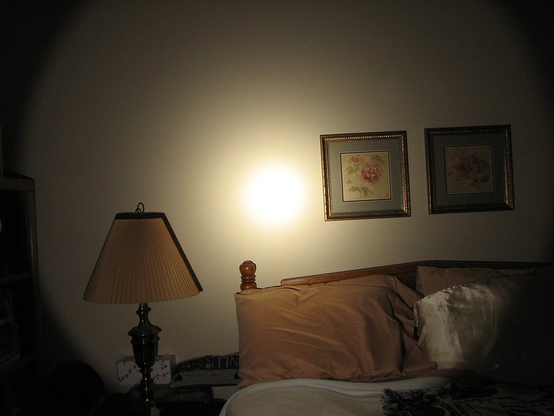
What about the beam shots? Ok, I put in 2D cells (Alkalines). It's plenty bright and brighter than the stock light, But.... DO NOT stipple the Reflector!! It turns it into a Mule. Well almost. It almost eliminates the entire spot all together and turns it into all spill and adjustment has no effect on it. Turn all I want and it's still all spill.
So, Jack, that answers your question. Do not stipple the reflector unless you like the beam in the photos.