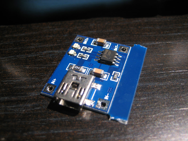
I realise that some people would prefer a micro-USB socket for the power supply input , but I’m happy with a mini-USB socket … I am only using my four for 18650’s with a one amp charge current , so I don’t need to change anything … To change the charging current , you need to change the value of one resistor.
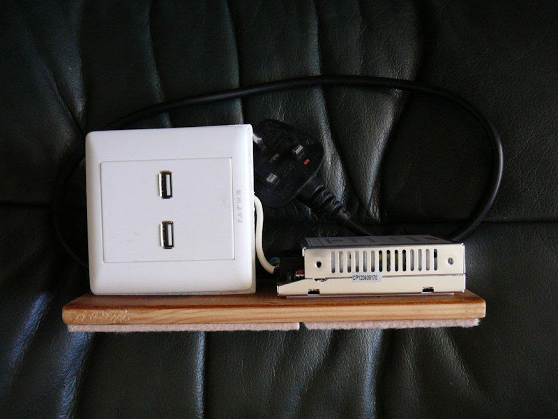
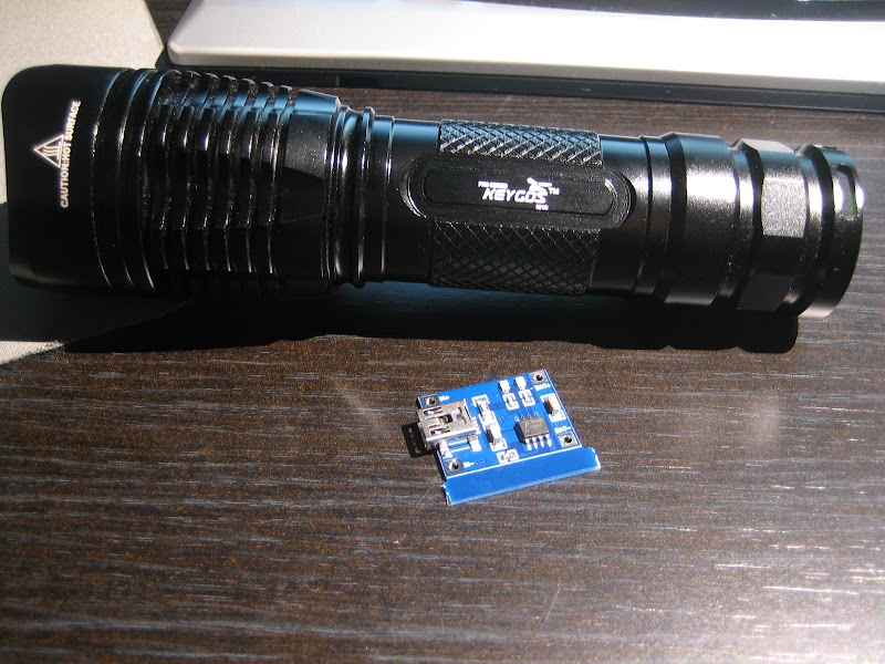
At about £1-12 each (or thereabouts) , these are ridiculously cheap Li-Ion chargers … Obviously a 5V PSU is needed , but these 1A plug-in USB units are available cheaply on Ebay and the short USB to mini-USB cord is cheap too … I made up a 5V 4A switch-mode PSU with four USB sockets attatched , rather than use several of the small 1A plug-in units … Two leads have to be soldered onto the charger board , to attatch to the battery (mine use croc-clips and magnets) and that is all there is.
They apparently have the correct CC/CV algorithm , though this does need to be proven.
Perhaps some kind person could do a proper test on these boards … It might encourage some Li-Ion users to have a go at making a few “dirt-cheap” chargers.
The chip does get a bit warm , but I am assured (on other posts) that this is perfectly OK.
.
I have some on order and will probably test them at a 2 or 3 different currents. I expect them to use the correct CC/CV, but (like the ML102) they will probably have a slow transition between CC and CV.
Thanks HKJ … I look forward to reading a definitive test on these cheap charger boards … I only use them for my 18650’s , so I leave the charging current set at one Amp … I connect to my batteries with 4” leads fitted with (soldered on) shrouded croc clips … I clip the crocs onto magnets … I find that the magnets with a countersunk hole in the middle are great for this purpose … The larger side of the magnet hole fits over the positive battery nipple and is in good contact … The smaller side of the hole is outermost so the croc-clip stays on OK.
I hope your findings justify my liking for these boards … I will still use them though , particularly now that I know that the chip temperature is not excessive.
.
If you are only using one charger then you could buy a plug-in 5V USB PSU with an output of at least one amp. I did this initially but since I have four of the charger boards, I needed something better … I usually only use two chargers but I decided to provide power for four devices whilst I was at it … I can charge my DAB radio and other items on this at the same time as I charge the batteries if needed.
The chip on the charger boards does get quite warm during the early part of the charge so you might want to add a heat-sink to the back of the board. This isn’t essential as the chips will work at quite high temperatures … I just wanted to keep the temperature down a bit as the chip will reduce the charge current if it gets too warm and then it would take slightly longer to complete the charge cycle.
You don’t actually need a battery holder … If you solder two six inch leads (Red and Black) to the charger output and solder croc-clips to the other ends , you can clip onto small magnets which will “stick” to the ends of the battery … This works very well and all my charger boards are done this way … Initially I tried soldering straight onto the magnets , but the heat reduced the magnets attractive force … Hence the use of the croc-clips.
I can’t put photos on here but I can email one if you wish.
Different makes of cells will terminate at slightly different voltages , possibly because of differences in internal resistances of the Li-Ion cells…. I now only use Panasonic 3100mAh and a couple of EXTAR 2600mAh.
My boards are all about 4.17V to 4.18V … I prefer to be slightly below 4.2V rather than above … It only makes a few minutes difference in use in a torch … I guess that storage of cells is slightly better below 4.2V than above.
I tried soldering to magnets and even adding second magnets but I find it better to solder onto croc-clips instead … My flexible leads are only about 4” long plus the length of the croc-clip … I use magnets with a countersunk hole in the middle … The croc-clip clips on easier with one jaw in the hole and other jaw on the magnet rim … I have tried other ways of connecting with other shapes of magnets but I just find these countersunk ones to be better … Personal preference.
.
I found a 5V 550mA charger with mini-usb, is 550mA enough to charge a single 18650? I should also have a usb to mini-usb cable, but doesn’t a usb port only put out about 500mA?
Where do you get your magents at/from? Can they be scavenged from something? I have wire and a soldering station but no magnets.
march.brown, thanks for the description of your power supply, but a picture would help me understand what you did better. If you send me some I can post them here for everyone to see. I’m interested in seeing how you have all of these hooked up.
Get a USB wall-charger with a normal USB socket on it , not a mini-USB … Use a normal USB to mini-USB short cord …I would go for at least a one amp wall-plug USB charger , preferably higher as the unmodified charger board will charge at one amp … For 18650’s I only ever use one amp charger boards , so there is no need to change the resistor on the charger board … I don’t use my chargers off USB sockets on my PC … That would limit the current … The reason that I made up my four-way PSU was that I can charge up to four batteries.
Get two pair and some insulation and make connectors that will avoid short-circuiting.
Make one pair with the electrical contacts only exposed on the “N” magnet faces, and another pair with the electrically live exposed metal being the “S” faces.
Make the rest of the connector insulated so only the face is bare.
The faces being the same repel, so the connectors won’t want to short-circuit. They’ll still attract magnetically but it’ll will pair up metal-to-insulated.
I’ve bought 2 of them, haven’t used them for now, my question is, if it would be a problem, using them at 500mA? Will it charge slower, or will it run out of regulation or turn the magnetic field of the earth…
Wiring with magnets seems to be dangerous to me, except, it’s insulated the clever way. I have a very shitty DX-Charger, perhaps I use the housing. Or I put it inside a 5,25”-PC-tower-slot with 5V-internal supply. You could put them in a bigger flashlight, drilling a hole for mini-usb… Or build a charger for 2nd battery of your smartphone inside a cd-case… lol (for an emergency-power-charger/external battery there are other boards available on ebay, with 5V-output built in…)
(I have 2 very good XTAR-Chargers for my 18650s, but I could not resist buying…)
The intention is to eventually put a plastic shield over the naked mains connections … As I am the only person to use the PSU , it is something that I will eventually (one day) get round to … I will probably put a tightly-fitting piece of plastic in the space between the PSU and the USB sockets … I will have some hidden carefully in the garage somewhere , as I don’t throw any useful rubbish away.
.
To put every safety-minded persons mind at rest (including fartybum) , I have now fitted a clear plastic shroud over all the terminals … I just happened to be in my garage when a suitable piece of hard clear 2mm thick plastic appeared … I have fitted the shroud only over the terminals and with access still available to adjust the PSU voltage potentiometer if needed.
If ever (whenever) the PSU is eventually handed down to another generation of flashaholics , it is definitely fitted with a safety shroud.
.
s. My garage is not a car garage , though if all my useful rubbish was cleared out I suppose it could house a car easily … It also used to house my three motorbikes , but since I no longer “bounce” (age related) they had to go … Shame really ’cos motorbikes never stop loving their owners … The garage is far more useful as a workshop though , as I don’t have a shed to put my router and all the other woodworking tools plus mega amounts of garden tools , chainsaw , ladders etc … It is also a nice warm place to work in , away from the TV.
.