I going to stop short of calling this a fail; you decide for yourself.
I highly recommend that only qualified DIY hobbyists attempt this, and if you are not qualified, and your concern is also raised, find someone who can do this reliably.
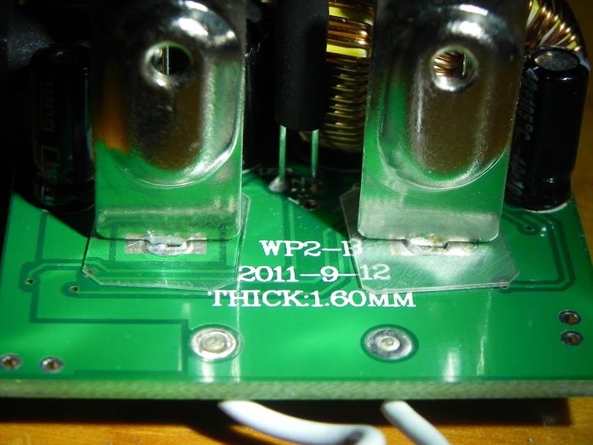
Problem statement: The positive tabs in the XTAR WP2-II chargers (earlier and later models)
seem to have a slight oversight in the PCB payout process. This was pointed out in another thread but I believe it deserves its own thread. I have notified XTAR through PM of the other thread as well.
Please look carefully at the trace the left and right of the left side positive tab. Notice how it “hovers” over the alternate trace. Same with the left side of the right tab. Since we always push the cells in by engaging the negative end of the cell, the positive end is pushed down. This likely puts force on the charger’s + tab as we engage the cell, particularly with longer 18650 protected cells. the installation and removal of the extension buttons could work the tab also where, over time, the solder mask could wear away (very thin) and cause a short. Having lost one charger already after two years of great service, I don’t want to loose another. I depend on this charger on a nearly daily basis.
Once I opened the charger, I noticed there was not enough clearance to simply put a shim under the edges of the tab so I determined I needed to remove the tabs. I cut a small mylar washer and placed them under the tab and re soldered them. This looks easier than it is. Removing the tabs and the solder should be done with care so nothing happens to the pads and you need to remove all the solder before re-assembing to avoid trace damage. The tabs are quite unwieldy when re-installing them. I ended up holding them in place (one at a time) and tack-soldered it. Added solder to the pad and finally flowing solder with a bit of flux to get a good solder joint.
I am not flaming XTAR in this case. I simply want people to know about this as I very much appreciate both the overall performance of this charger and the person who posted the initial post in a review thread for the newer charger. That is why I wanted to be sure this had its own thread.
Before:

After: