So I understand the XM-L2 has a higher vF (forward voltage) than the XM-L and is best fitted with a 2 Li-Ion cell driver / host. What happens though if I pair an XM-L2 with a single Li-Ion cell and a driver without boost? Will I get less output than a standard XM-L (in the same host with same driver)? Is it still an improvement over the XM-L? Figure a typical good 18650 (say Panasonic NCR18650A 3100mAh). And would there be a bigger improvement with a lower internal resistance cell (Panasonic PD)? Wouldn't runtime be less on this XM-L2 light since the battery will sag below the vF requirement faster?
I'm expecting that there would be some improvement, but not the maximum improvement that there could be. Any idea how much gain I'd get? Basically, is it worth it? Could you end up with a case where the original XM-L is better suited for a light? Such as for more desired runtime?
As long as the voltage fed to the (linear) driver is higher than the Vf of the led at the given driver current the output of the XM-L2 is great. The driver will however not see the resting voltage of the battery but the voltage under load, combined with a voltage loss caused by other resistances in the flaslight (like the switch), on a fresh li-ion under 3A load the voltage can be already as low as 3.8V (depending on quality and type). Because the Vf of the XM-L2 is not that much lower, when the flashlight is left on, this Vf is soon reached and the current through the led starts dropping (I assume a Nanjg-type linear driver). The vf of the XM-L is lower and the battery can be drained further before output is dropping.
So this confirms my expectation that the XM-L2 will be brighter to start, but dim quicker than the XM-L and therefore have shorter runtime. So a person looking for maximum brightness over a maximum runtime should choose XM-L over XM-L2 (for this single Li-Ion setup)?
I've posted many times, maybe you missed it (maybe I'm nuts ??) but if you use a high amp, low resistance cell - it works! I've measured some great numbers on single cell, XM-L2 U2/SinkPAD lights using a Panasonic PD, Samsung INR 1500, or best tested so far by me: Samsung INR 2000. The Sam INR2000 is the lowest resistance cell tested by HKJ.
The criticism, may be justified, will it work for 5-10 minutes and not just the first 30 seconds after a full charge? Good question - I think they hold pretty well - didn't do formal tests of that though.
There are posts saying - no, no good, XM-L2/SinkPAD are only good for multi-cell battery lights - yes, maybe better, but my meters don't lie over and over again, comparitively, across several custom build, etc.... The truth is in the doing, seeing... Opinions, congestures, lack of proper measuring, ... are not evidence.
Sorry to go off a little, but sometimes I feel like I'm posting/talking to a wall. Until someone validates/confirms what I do, it's not goning to be taken seriously. Fortunately relic38 did just that with a HD 2010 build. See the last few posts on this thread: https://budgetlightforum.com/t/-/15778.
I would sure like to see side by side comparisions of an XML U3/alum star light at 3.85A compared to an XM-L2 U2/SinkPAD at 3.85A over time, when the XM-L2 light is using a Samsung INR 2000 or Panasonic PD. Both of course will sag from start to 10 minutes. Of course another test would be to run them for 10 minutes. Turn them off, let them cool, with the same depleted batteries, test again for 5-10 minutes.... I would find it hard to believe the XM-L2 light will fall below the U3 light from what I'm seeing on partially depleted PD's. Ok - I'll have to do this test... I got C8's that fit the bill here.
Tom,
Yes, I have read your posts (well, some - wasn't following the thread you linked, but read those last few posts) and that was where I was pulling some of my expectations from. In this scenerio it will not be a sinkpad, nor do I want to use this as a "low internal resistance cell only" light. I want it to be a regular, everyday, throw just about any ol' 18650 in it (I only buy decent ones) kind of light. I was just stopping briefly to consider an XM-L2 vs. an XM-L for it.
So in this case it sounds like I'll stick to the XM-L. If I were wishing to mod into a really high output and/or super thrower light, then yes I'd go XM-L2 with dedicated low internal resistance batteries. In those lights I wouldn't be looking to get max runtimes either.
Understood - I don't know, everything I'm reading about the single cell issue seems to be theory and I'm just not sure that's how it really plays out. In fact I'm using an XM-L2 T6 3C in my BLF mini, replaced the XML T6 3C, and I feel it maintains brighter output through-out the run of the battery - just using a DLG unprotected from KumaBear. If you compare XM-L2's to XML U2 or U3's on a straight, stock alum star, I just don't seem to see those poor performance issues everyone talks about in theory. Maybe there's some posts with real measured proof I'm unaware of.
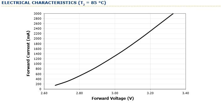
Just posted this over in the XM-L2 Vf thread. Here is the Cree datasheet graph showing current/Vf for an XM-L2:
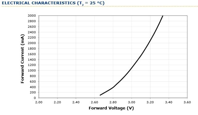
Here is the Cree datasheet graph for the XM-L for current/Vf:
Here is HKJ's test of the Keeppower Protected Panasonic 3100mA NCR18650A at 3A load (photo taken from the 18650 Comparator):
This next chart may be better. Taken from HKJ's review of the same Keeppower 3100mAh:
So comparing the charts, it seems this battery under a 3A load with an XM-L2 (which has a Vf of +/- 3.32v at 3A) should drive the XM-L2 at this output for about 33 minutes? When I look at the Vf chart for the XM-L it looks like at 3A the Vf is nearly the same! I realize the charts are done at different temps, does this explain why they are appearing the same? Now I really am confused! According to these charts it seems that if anything the XM-L wants a higher Vf than the XM-L2!
I think a lot of the conjecture stems from Match's (admittedly inaccurate) Vf graphs. The CREE graphs to which PilotPTK and Garry linked show a more promising curve, TBH.
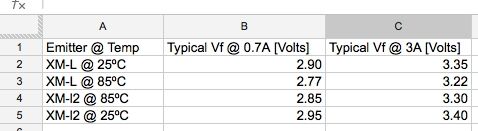
What's really nuts is that if you look at the CREE data sheets, the forward voltage spec for the XML is actually higher than for the XM-L2!! XML @3A = 3.35, XM-L2 @3A: 3.3, these are both "typical", again though, at different temperatures I'm sure. If we're not confused enough...
djozz - where did you get your vF numbers from? I seem to recall some specific numbers posted, but not sure if it all originated from Match's post that was deleted. Could be someone did the temperature based conversion.
I'm very interested in getting to the bottom of this too - got a lot of builds/mods coming up and don't want to waste anyone's money, time, or just mis-lead anyone...
I think people are worrying too much about possible meter readings rather than how a light works for its purpose ie giving light in a dark place. I dont know about other people but that’s the important thing for me.
What I did notice is same cell and driver, an xm-l pulls 3.7a xm-l2 pulls 3.3a and looks brighter. I’m happy with that and will stop worrying.
I basically agree, but figure you are talking up to about $10 in parts difference (XML U3/basic star vs. XM-L2 U2/SinkPAD), and whether it looks brighter only for the first minute, then remaining time looks duller plus a shorter runtime - sure would be nice to know the trade-offs going in, pros and cons, so we can accurately answer these questions, like what Garry is asking here. Also for me, it affects your decision on amps and drivers, if 3.7A is unachievable, then 3.4A driver setup is fine - don't add extra 7135's or bother gping to a higher rated driver.
You are correct; one must consider the different junction temperatures at which the two emitters are spec’d. I made made this quick spreadsheet to illustrate ramifications. Keep in mind these are “typical” values. I wish Cree would disclose normal distribution data. If they did, the term “typical” would carry some meaning.
what we do know is that a neutral xm-l2 will put out about the same lumens as a u2 @3a.
So I can now have a nice tint AND high output with lower running current - less load on the cell and switch components, cooler operating temperature.
Or put another way, you could now have an xm-l2 edc at for arguments sake 2.5a and have similar output to an xm-l at 3a (same bin emitter) again, less heat, so a longer run time on high.
I stand by my point, some people (none in this conversation I will add) are too busy worrying about the theory instead of looking at the practical reality, or playing to the new emitters strengths ie higher output from a nicer tint, that for me is the xm-l2’s forté. :bigsmile:
Plus OP meant without buck.
If you have a driver with boost, good luck haha, as it’s probably for 2 emitters in series and you would connect it to a single emitter, over voltage, emitter death.
I did not mention numbers, was just trying to explain what is going on assuming the vf of the xml2 is higher than xml. And I must admit I am not sure where exactly idea came from, could very well be from match's retracted graph (@3A his graph gives a vf of 3.7V, where Cree claims are between 3.3 and 3.4V, that is significant different.)
Slim Pickens posted the vF numbers which are interesting, reversing the roles which is what was expected. What's also interesting is the lower the temp, the higher the vF which is what we see with SinkPAD's. Did an interesting test: C8 w/XM-L2 U2/SinkPAD 3.85A Nanjg, and C8 with XML U3/stock star 3.8A KD V2 - used same fresh charged LG 2400 mah batts from a Dell notebook pack pull. These batts seem to be average resistance (they take long to charge also).
C8 w/XM-L2 measured 3.4A, C8 w/U3 measured 3.8A. Simple wall and ceiling eyeball test (3 opinions) agreed the XM-L2 light was brighter. This match's what Gords is saying too.
I made a XM-L2 T6 3C drop-in with 11 380mA chips (4.18A) the best I can get is 3.86A with fresh off the charger unprotected Sanyo 2600 @4.20v but the current drops immediately and about 10 seconds later my battery is down to 4.17v and the current is down to about 3.7A
Guess I need a stout IMR/INR type cell.
BTY xm-l2 @ 3.8A is bright after about 10-15 minutes 3.2A-2.8A it’s still bright enough to light up the whole back yard.
I plan to do the same. Would like to compare with the driver I mention below. Would be cool do to same test with XM-L and XM-L2.
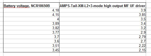
I used the XM-L2 (U2 KD claims on their drop-in, I don’t trust that store). Replaced the driver with the high output 3-mode Ultrafire driver. (Came with a popular P60 about a year ago)
-Capacity-3.0L.png)
/Keeppower%2018650%203100mAh%20(Black)-CapacityTime.png)