
4.6 out of 5.0
XM-L T6 Bikelight/Headlight from LightsCastle
I would like to extend a big Thank you to LightsCastle for sending this light for review. Check out their Website here https://www.lightscastle.com/
Mfr Specifications
Brand: OEM/Generic
Model: XM-L T6
Emitter Brand: Cree
LED Type: XM-L
BIN: T6
Color: Red/Black
Number of Emitter: 1
Voltage Input: 8.4V
Battery Configuration: 4 x 18650 Battery Pack (included) Unknown mAh
Circuitry: 2800mA (Manufacturer rating)
Brightness: 900 Lumens (On Box Packaging)
Runtime: 3-4 hours (manufacturer rated)
Number of Modes: 3
Mode Arrangement: High > Low > Fast Strobe
Mode Memory: No
Switch Type: Reverse clicky
Switch Location: Rear of Light
Lens: Glass Lens
Reflector: Aluminum Smooth/SMO
Beam Range: 200m approx
Strap Included: Headband + Bike mounting rings
Dimensions: 2.13 in x 1.65 in x 1.65 in (5.4 cm x 4.2 cm x 4.2 cm)
Weight: 650 g
Price: USD $47.92 Use coupon code 4F6YT for $10 (10 USD) price reduction
Crystal from LightsCastle sent out this light on April 11th. I received the light in perfect condition only 8 calendar days later on April 19th. That's very impressive indeed from China!
The light arrived very well packaged in it's own box. Securely wrapped in a dedicated Bubble-Wrap plastic envelope.
This parcel was sent to the UK via HongKong Post.

Upon opening the packaging, this was what I found inside.
The Box

The Contents, neatly packaged inside.

My son took a keen interest in the light so we decided to take it out for a few inspection shots. Here it sits in Headlamp mode.
As you can see, the light mounts to the headband in much the same way it mounts to Bike handlebars using the flexible rubber ring.
The headband has a supporting center strap which sits over the wearer's Bike helmet, or head.

A shot of the battery pack showing the strong securing Velco strap for securing to a Bike frame.

Another shot of the battery pack, this time showing the strong securing battery strap and the belt loop (If using light as a headlamp)

let's take a closer look at the light itself.
The Exterior
As you can see, the light is a self contained unit with the switch at the back and a removable bezel at the front.

The Anodizing is absolutely flawless, both on the main body of the light and also on the bezel. I would be willing to go out on a limb and say it's almost certainly HAIII Hard Anodizing.
This next image shows a closer look at the anodizing. You can also see the excellent machining, especially around the heatsinking vanes.
Perhaps they could be a little deeper to help with heat dissipation over longer runtimes but they do seem to cope well.
With the added help of continued airflow when riding, all of the tests I have ran so far have not highlighted any excessive heat issues.

The reflector is of a very high quality finish with no imperfections to be seen, even upon close scrutiny.
The glass lens, although uncoated is tempered and also of a high quality with zero marks or imperfections.
The reflector in this light is 38mm Wide and 25mm Deep
The LED was a little off from perfect centering when I received the light, as can be seen in all of these shots.
With a bit of fiddling around later-on, loosening and retightening the bezel, had it perfectly centered in less than a minute.

The mode switch has a very positive feel, it clicks with a clear audible tone even with a light press.
The rubber switch boot is soft and flexible, offering good grip while not feeling spongy in any way.
If we look at the waterproofing aspect of this light.
LightsCastle themselves do not make any claims about it being waterproof but the manufacturers state in the instruction manual that the light can be used in 'Driving Rain'.
I would say that this is probably an accurate description due to the watertight seal arrangement on the front lens (More on this later).
It must be noted though that this light is certainly Not capable of being submerged into water of 'Any' depth due to the arrangement of where the wiring enters the light underneath the mounting bracket.
With that said, the chances of water entering the light from normal (rainy) use are very slim.
Below is the mounting bracket arrangement along with an image of the bracket removed, revealing the unsealed hole for the wire entry point.

Now here is my first complaint and really it's just nitpicking.
I'm not really sure why the manufacturers didn't introduce a surface with more grip under the mounting bracket as highlighted above.
Either gluing or impregnating some rubber to the surface would have helped immensely to avoid drooping of the light when hitting bumps.
The problem is easily solved though with some insulation tape around the handlebar prior to fitting the light.
Let's take a look inside the light.
The Interior
Removal of the bezel reveals the lens and reflector, along with a visual clue to how well the front of the light is sealed to prevent water entry.

The front glass lens is pressed very tight against the top of the reflector which compresses the sealing ring behind the bezel.

The other end of the reflector (The LED end) presses very firmly against a plastic isolating ring.
This in turn forces the MCPCB (LED Star) against it's backing plate (The Pill Heatsink plate) - More about the isolating ring and pill heatskink below.
The threads for the front bezel, while not quite square, are fully anodized thick and course.
When removing and replacing the bezel, the threads feel very smooth and precise.
The rear sealing ring for the bezel is exactly the correct thickness and offers a good amount of resistance for a watertight seal.

Strangely, both bezel sealing rings glow in the dark !
If we take a closer look at the back of the reflector, you'll see that it has a soft and pliable, non conductive ring (it looks like Mylar)
This appears to be intended to help with centering of the LED upon re-assembly.

With the lens and reflector removed, we can take a look inside the light housing to reveal the LED itself.
It is surrounded with the plastic isolating ring which serves a dual purpose.
The isolating ring prevents electrical shorting on the back of the reflector, while simultaneously keeping the LED Star pressed firmly against it's heatsink plate.

By removing the Pill retaining ring (as pictured above) with needle-nose pliers.
The entire pill can be removed from the housing.

With the plastic isolating ring removed, we're able to see the MCPCB (LED Star) mounted to the pill heatsink pad with thermal compound.

If you happened to notice that the heatsink plate tapers away at a 45 degree angle - this is intentionally so.
It allows the plastic isolating ring to sit lower into the pill so that full pressure can be applied to the LED star with the back of the reflector.
At least two thirds of the LED Star is still in contact with the pill heatsink plate, and where it matters most, directly under the LED.
This doesn't seem to cause a noticable loss of thermal transfer effect as the body of the light heats up quickly without an observable reduction in output over a ten minute run.
One initial concern was that due to the wiring, the pill itself cannot be threaded into the body of the light.
Instead, the pill sits on an inner lip of the body housing. (Highlighted below)
Apologies about the focus, my auto focus camera flat out refused to focus on the lip despite numerous efforts, but you'll get the idea.

While this arrangement arguably offers less thermal heat transfer between the pill and the body of the light.
I think what the manufacturers have done in this instance is a good compromise.
In order to maximise the thermal transfer, the manufacturers have deliberatly made a considerably thick retaining ring with strong course threads.
I have found that this allows the pill to be pressed onto the lip with a very considerable amount of force.
You really can crank the pressure down on the retaining ring without fear of the threads slipping, and it really does seem to work well.
The outer body of the light begins to warm noticeably within 30 seconds of turning the light on.
The image below highlights the thickness, and the threads of the pill retaining ring.

A quick look at the back of the pill shows the driver PCB and switch assembly.
I like the brass insert which allows the driver's outer contact to be directly soldered.
You may consider adding further solder bridges to this driver (as I will be doing)
I've highlighted in the image below some locations where it's possible to make new solder bridges.
Also highlighted are the two LED's on the driver PCB.
The green LED lights when the battery charge is good. The red LED lights when the battery needs to be charged.
I like this idea a lot.
Since the rear LED is clearly visible when riding, it gives plenty of warning without being caught in the dark (literally)

With some fiddling around I did manage to take some (Simulated tailcap) amperage readings.
(please note that readings are approximate and not taken from the LED, but inline with the power connector)
High:
970mA (2S2P cell config) 970mA x2 = 1940mA - driver efficiency losses = LED current Approx 1600mA - 1800mA Mfg claims 2800mA
Low:
265mA (2S2P cell config) 265mA x2 = 530mA - driver efficiency losses = LED current Approx 420mA - 520mA Mfg claims 1500mA
Despite the much lower than claimed driven emitter, the light does put out a lot of useable light. (More about this explained with the beamshots)
Try as I might, I cannot reproduce any visible signs of PWM on this light. In both high and low modes it is entirely PWM free.
I will try to remember to update this review after I have resoldered the driver outer ring and taken a closer look at the driver components.
It would seem that the driver regulates output in a linear manner.
The switch is a forward clicky type which feels crisp and positive when clicked.
There is no mode memory on this light. Each press of the switch will always activate the next mode.
This means cycling modes to return to the 'Off' position.
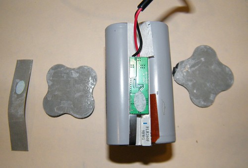
The Battery Pack
The battery pack is utilizing 4x 18650 cells in a 2S2P configuration. There are no markings on the pack itself to indicate mAh.
There are no mAh claims on LightsCastle website for this light either, so it really is an unknown at this time.
I was happy to see good quality cable used between the battery pack and the light. The images below will highlight this.
Upon receiving the light, the measured voltage of the pack was 7.57 Volts.
Fully charged the pack measures 8.42 Volts.


The charger for the battery is a generic 'mains chopper' type charger.
The battery lead plugs into the charger. When the battery is charging the light on the charger is red.
When the battery is fully charged the light will turn green.
The charger will cease charging the battery pack when it senses that the pack is fully charged.
*you will need a mains adaptor suitable for your location as it's not supplied*


Before I upload the beamshots and talk about my final conclusions. Here are a few size comparison shots.
Here is the light alongside my old Zippo lighter

Here is a front lens/reflector comparison shot next to a Jacob A60

Here are a couple of pics of the light and battery fixed to my son's bike. (please excuse the rust)


I'm absolutely certain there's a whole load of things I've forgot to mention so please feel free to ask any questions.
Thanks for reading guys.
Beamshots, thoughts and conclusions to follow.


 .
.