Protected NCR18650B x2 (No physical alterations to the light, just a tube for the batteries) - Improvised and made one out of rolled up presentation paper cut to length, works great. These two 69.5mm batteries fit with no spacer needed.
Data
Stock DST 1.55 Amp, 3 C
Stock MH40 Thor 1.8Amp, 2x NCR18650B 3400mAh Protected
Dedomed XM-L DST with 5amp driver, 5.2 Amps at the tailcap, 2x NCR18650B Protected
XM-L2 with 5amp driver, 5.6 Amps at the tailcap, 2x NCR18650B Protected
With regard to the emitter and dedoming, also keep in mind that on top of considerably warming the colour temperature it introduces quite a lot of green into the tint.
A 1C tint is already on the green side so I would recommend going with an emitter that has as little green in it’s tint to start with.
I’d get this one instead. XM-L2 U2-1A
2 cells will make your life much easier. I don't have a driver to recommend that fits the stock pill. The one you mention seems to have a strong following. Hopefully, someone can give you some good info.
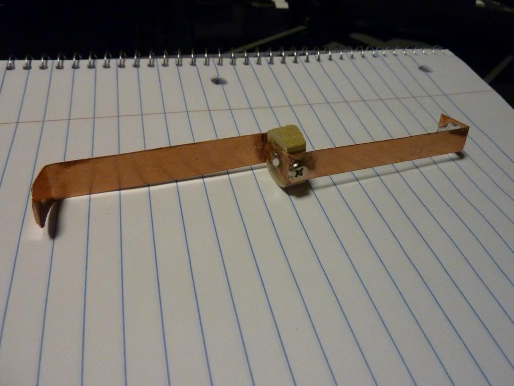
If you don't need modes, you could go parallel cells and direct drive (no driver). You just need to get the emitter on copper and have it well connected the light thermally. If you do direct drive, you could get rid of that crazy long driver spring and solder the positive wire directly to the switch. Then you just need to ground the led negative. Here is a pic of a good diy parallel cell holder that dchomak made for his DST (Post 562 of this thread):
EDIT: I'm saying this part more for other people that may read this post. If you go parallel, be very careful to not accidentally create a short. You sound like you already know that could be a very bad thing. You want to make sure you always put the cells in the above rig facing the same direction and to put the above rig in a insulated tube. You need a spacer anyway since the 18650's are quite loose in the DST tube.
I did not know that about the green, thanks for the info!
About the parallel, I saw that neat device in the giant thread, but I think I’ll stick to a driver and modes.
I think 3/4” would be extremely tight with 2x protected 18650? I’m seeing about 48mm per defiant c, sitting in the tube they have about 1.5mm clearance from the threads the tailcap mates to. The 2x NCR-B are about 7mm total shorter. The spring just barely starts to compress when the tailcap is fully tightened on the 18650’s so a spacer is probably a good idea.
I haven’t read much further into spacers aside from the dowel for 1x and of course the sex bolts.
edit: perhaps one of those 16—- spacers from FT? I can’t remember their length atm…
Have you looked at the length of the springs at both ends and how much compression is available? You might want to allow room for unprotected spares at some time in the future, so that adds a few mm.
1/2 inch is 12.x mm and I wouldn’t go any shorter going by eye based on the parallel rig I built (I’m using unprotected)…… also, my single cell dummies are a good bit longer than a single cell is. Like others of us you may end up with more than one cell arrangement and I have spares in each size, too.
You said you need to buy the wrap, so buy both sizes of T-bolts and take back the one you don’t want next time you go back to the store
Maybe use a paper towel cardboard and some tape wrapped pennies to build models and lock down what you want to do. It’s going to vary a bit base on how much tension and what spring you end up with after driver and other changes anyway.
If you use 2 x lithium you can direct drive a mt-g2 (no driver). You’ll need a space since 2 x 65mm is much shorter than 2 C batteries. Maybe if you used 70mm xtars.
Here is a great thread showing how to mod the Nanjg 105C/Qlite driver to run on 2S Li-ions. Post 1 by DBCstm shows the modifications clearly. Later in the thread, part numbers are listed.
You can easily make the 17mm driver fit the DST by soldering a wire or copper braid around the parameter of the driver.
EDIT: Sorry forgot link. Added above. Thinking about this more, I don't think this would work with an xml. The 7135's would have to burn off a lot of excess voltage. It would be a good option if you went MT-G2 though.
I was looking into the mt-g2, I could have sworn there was a comparison thread, but I couldn’t find it. Any benefit in using it over an xml2?
If it helps I was also hoping to get 30-45min of constant output on max. I’m not a fan of constantly degrading output. I was using the stock DST last night for around 40 minutes and changed batteries mid use, the degradation was rather apparent. I was kind of surprised it never got noticeably warm which was awesome.
Based on what you seem to want from the light, you probably would not be happy with the MT-G2. It will cut your throw by a ton and a half. It would put out a ton of floody light with some throw. It would likely out throw the stock DST, but I get the sense you want more.
Here is a mouse over of 2 DST's. Mouse out is dedomed xml2 at about 7 amps (35 watts not counting voltage sag) to the emitter. Mouse over is dedomed mtg2 at about 6 amps (50 watts not counting voltage sag).
You got any existing lights that have a cool white U2 that you could swap out?
If not, I wouldn't worry about it. You can always upgrade the emitter later when it is back in stock. The DST is real easy to swap emitters due to the 2 part head. Just unscrew the reflector part of the head and you have complete access to the emitter.
Na I’m pretty new to led flashlights in general. No extra parts, or any sacrificial lights currently. This will be my first mod apart from throwing a light in the oven.
and yeah, I think I picked a good one for the first mod, super easy access to all the components. I guess I’ll wait on the emitter. I can fiddle around with my camera and try to get some decent pics to compare to the stock light to the dedomed stock emitter to the dedomed xml2 (when I finally get it).
I wouldn’t worry about using a 16mm mcpcb to replace a 20mm one, I tend to only buy 16mm emitters because they’re more universally compatible and fitting to larger pills usually isn’t an issue. Centering can be done with some wire wrapped around the pcb to function as a spacer but even that usually isn’t needed. Particularly if you have a decent centering ring on the reflector. If you don’t have any of those I’d recommend picking some up while you’re ordering parts, very useful
Any ideas how to get this sucker up in the 4-6 amp range (with preferably as minimal modification to the parts as possible)? I think somewhere around 5 amps would be sufficient.
@ 5 amps, 2x 3400mAh would be about 80minutes? So a bit less than 60 minutes runtime would be a reasonable estimate not knowing actual capacity?
A little late, but I used this driver lck-led.com - Informationen zum Thema lck led.. Gives 5 amps to the led. Mine wasn’t a 3 mode driver though it had 5 total with 2 flashy modes. |(
Never too late! I still have to grab a soldering iron, all those goodies involved with that, kind of hoping the emitter restocks while I’m getting everything in order.
I’m guessing the contact board didn’t fit? Did you have any issues with the heat involved at 5 amps?
I potted the driver in with fujik glue, no heat issues that I have observed. Seems like I did cut the pill driver resting lip out a little to fit the battery board. I cant remember for sure, but its in there and it’s not coming out with out quite a bit of work.