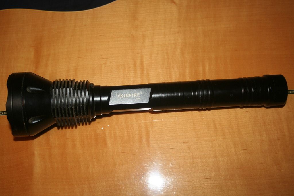
Howdy guys, I haven't done a build walk-through in a long time so I thought I would do one just for the fun of it. Plus Tom asked for some pics of me doing a side switch. I'm going to take a kinfire K34f and stick 4 Xhp-50's in it with a BLF driver.It's going to get a sideswitch. This is a big plunger light like the Trustfire 9x and 12x's. Same size light 2 or 3 26650's. Big head light but this one has 4 individual reflectors. No pill so that's nice. I don't know how the beam pattern will turn out. But I guess I'll find out.
I'll be running the light in 2x 26650 size and the emitters will be wired in parallel. Tons of amps so everything is going to have to be very heavy duty. Super good batteries will be a must they will be the limiting factor with the light.
Here are some pics of it right now. It's got a older school driver in it with XM-L2's two of them are high CRI neutral and two are cool white. I like it but it's going to get a tune up anyway.
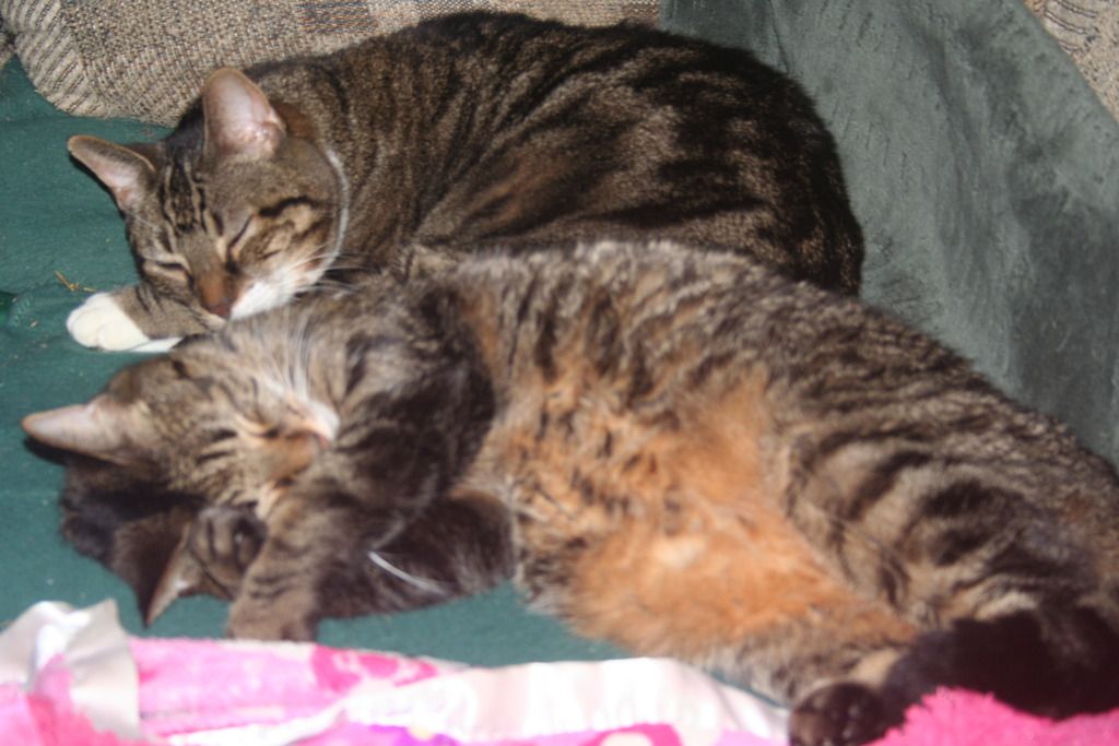
(partners in crime first)
All right guys I finished it up tonight and it turned out great. Right at 8,000 lumens and just tons of flood. The beam is really nice too. One big hot spot in the middle and the rest is just super bright too. 50kcd so not much throw and what there is is pure power throw.
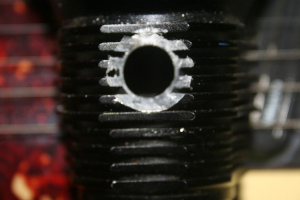
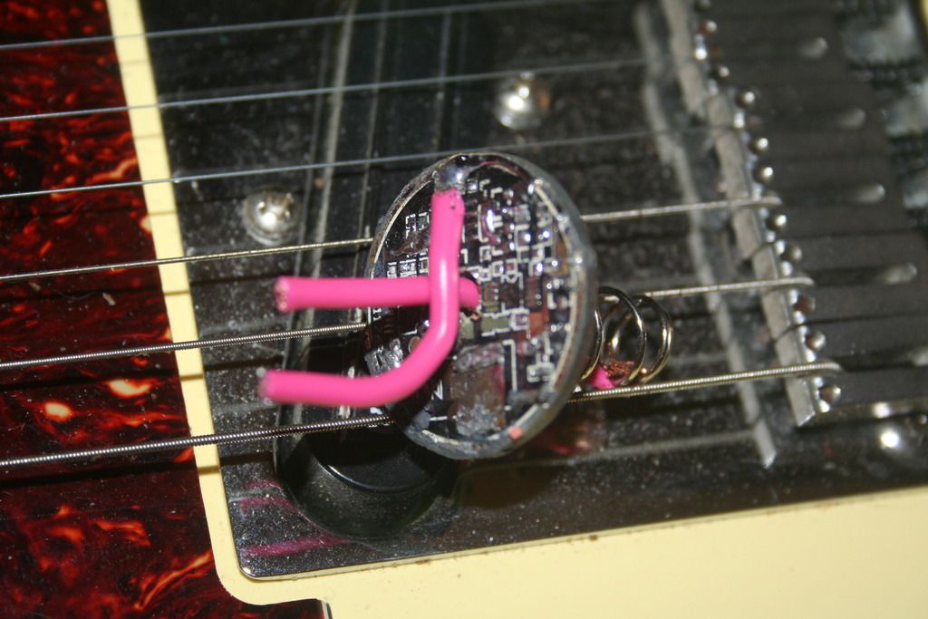
This pic is just the picture of the hole I drilled for the switch. I use a typical "button" switch. It's momentary "Clicky". To drill the hole I simply start with a very small bit and work by way up. As I get to the medium size drill bits I work it around it a circle to widen out the side a bit. The next pic is with it installed.
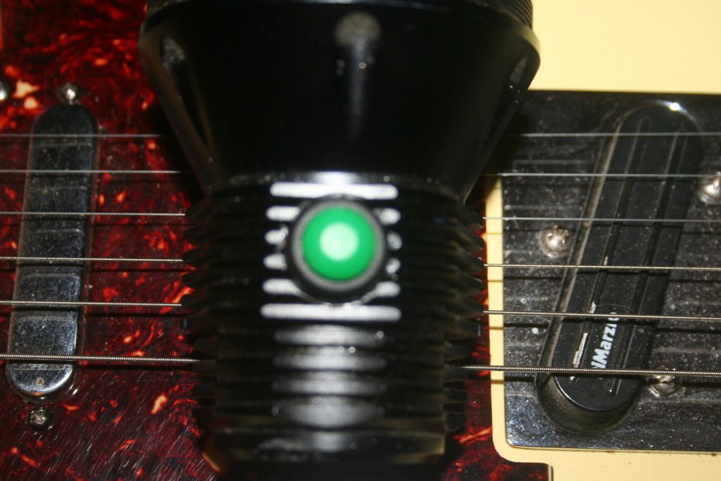
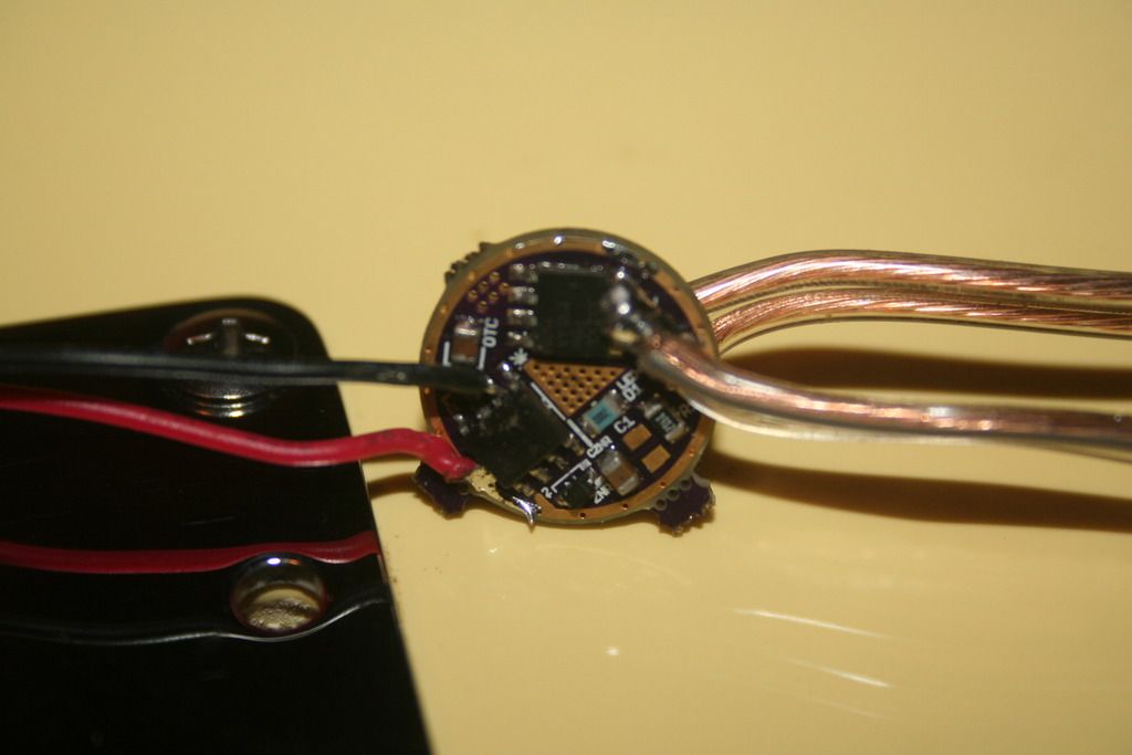
This is a picture of the driver I built for this light. It's a BLF FET driver that can be bought from Richard I'll put the link on the bottom. (non affiliate of course)For this light I used TomE's code in four modes. The light can be turned on High or Low depending on if you do a hold or a click.
There is a total of six wires here. Two on the negative end of the FET and two on the other side which is the positive side. The last two wires are for the side switch. One wire goes on the negate and one goes on the second pin of the MCU. It doesn't matter which is which, it's just creating a quick short to change the modes. I used 4 wires to run up to the emitters even though I didn't have to. I could have simply used two wires but it's easier to use thinner wires because they fit up under the reflector better than using two larger wires. Yes these are "speaker" wire. Don't laugh, they work great. 18gauge copper. You do have to be careful not to melt the plastic on them so they are not the easiest to work with, but I have no problems with them. They handle high current very well.
This driver will get two more very large wires as well. They will come off of the old driver after it has been stripped clean. That's the next pic down. As you can see I dill a hole through the center of the driver for the wire that leads to the new driver that is for the positive spring. It goes right to the top of the spring. The negative wire goes right to the side of the board so it will be making direct contact with the flashlight.
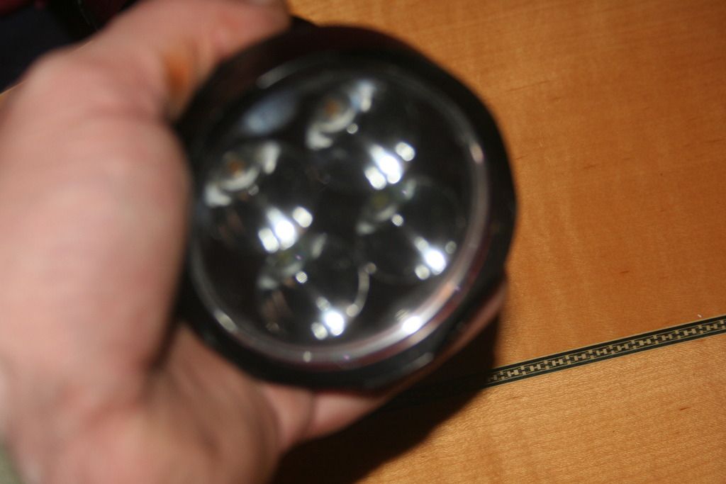
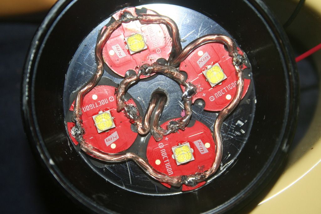
This is a picture of the emitters wired. They are wired all in parallel even though it's four wires. Negative is all on the outside and positive is all on the inside ring. Another reason to use two wires on each the positive and negative is simply to keep the current even to each emitter. The solder looks a little rough in this one but I did go back and add just a little bit to it. Wiring these can be a little tricky because as you wire one on the next one has a tendency to try and pop off. The trick it to. Pre-solder or "tin" the wires themselves and the contact points on the boards. Then you overlap them just a little bit. Also when I run the wires up into the light I leave them long. After that I pull them all up tight. Snip them as short as I can and then solder them on. Keeping the wire as short as possible will get you a little less resistance too.
One more thing to keep in mind. When I first set the reflector down on this the emitters where actually setting to high up in the reflector. I have found that working with these HXP's that you get a much better focus and can get rid of the dead zone in the middle by setting them just a little lower. I took the reflector off and added another small centering ring to the them just to lower them down and away from the reflect. It wasn't much but it made all the difference in the world. When they were too high up in the reflector it had a hole right in the middle of the beam. Now it's absolutely a perfect beam. And for the guys here that know me, I'm nuts about having a ring free beam. Can't stand rings.
I'll get some beamshots and some pics of the finished light tomorrow if it's not raining outside like it is now. Raining in the middle of December in Northern Michigan. Unreal.
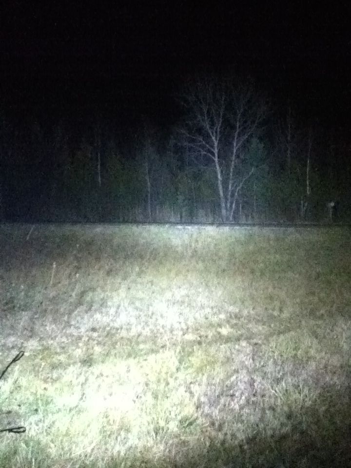
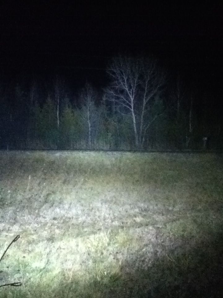
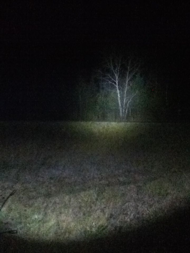
First beamshot is the 4x on trubo second one is high third one is another XHP-50 I built it's a single in a uniquefire UF-V8