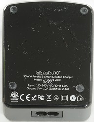
Caseflex 50W 6 port CF-AZ01-Z038
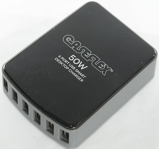
Official specifications:
-
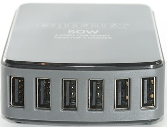
6 usb output ports
-
Total output 50W 10A
-
Each port can supply a maximum of 2.4A
-
SmartAmp works to distribute only the required amps to each in use port.
-
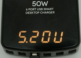
A built-in digital display is incorporated to let you see the real time output of both the ampage and voltage from the charging station.

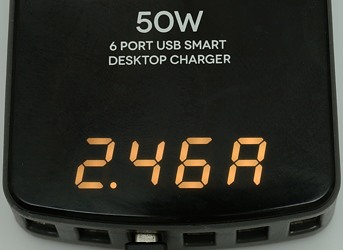
The build in display, the digits are not that bright in real life and the red color is not very visible, i.e. they mostly look gray.
Measurements
-
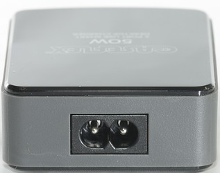
Power consumption when idle is 0.25 watt
-
Usb output is automatic coding with Apple 2.4A as max.
-
Voltage display changes between 5.18V and 5.20V, no 5.19V is shown.
-
Output voltage is 5.25V when unloaded
-
Output voltage is 5.18V when loaded with 10A (Measured on one unloaded port).
-
The internal display has red leds, but they nearly looks gray due to the box.
-
When a output shuts down it will not affect the other channels.
-
Overloaded outputs will recover automatic when load is removed.
-
Ground is common, overload disconnects +5V
-
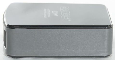
Weight: 184g
-
Size: 86 x 66.3 x 27.5mm
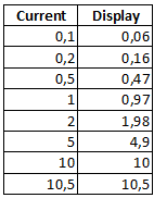
First a check on the precision of the build in ammeter. As can be seen it is not very good at low current, but gets better when the current is increased.
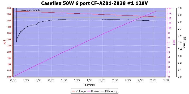
There is overload protection on the outputs at about 2.8A, this is fine for a 2.4A supply (The very good efficiency at the start was my fault).
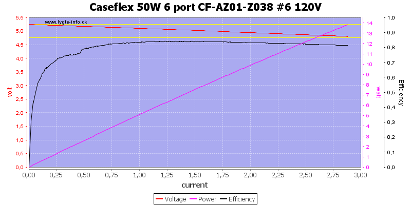
Another output looks about the same.
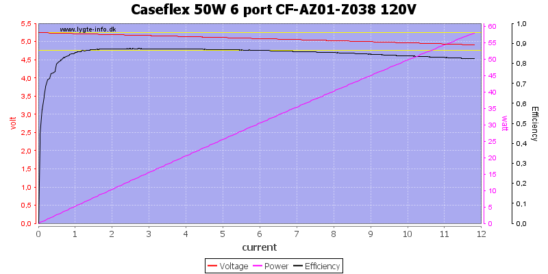
All port together can deliver between 11A and 12A.
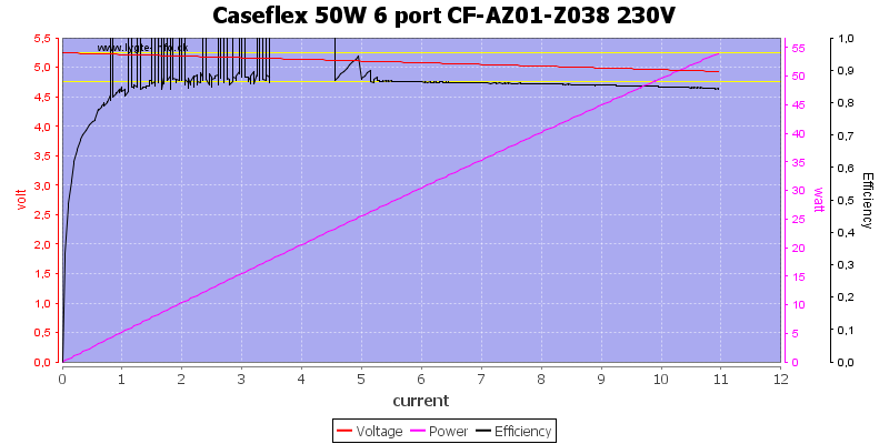
All the above curves was done at 120V, because they looked nice. At 230V the efficiency goes above 100%, that cannot be correct.
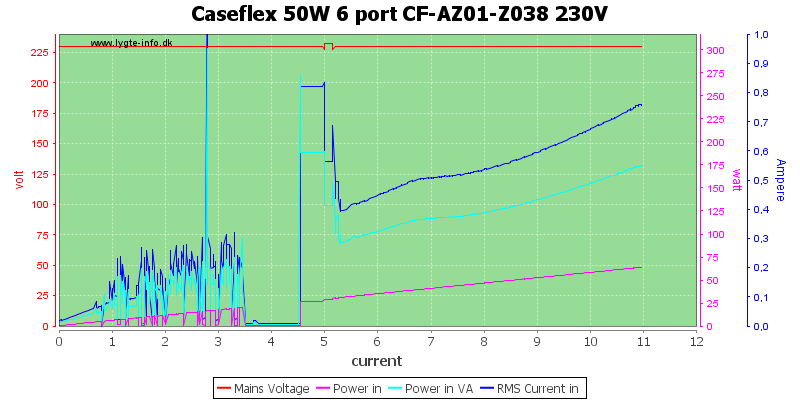
A look at the input power and current shows some strange jumps. My suspection is that the usb power supply is interfering with my AC generator and that is the reason for these strange results.
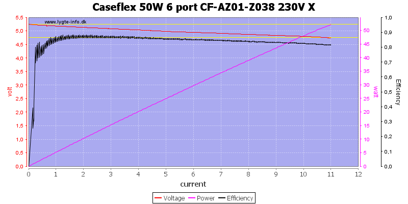
Switching to some other equipment gets rid of the strange current jumps and gives a much more reasonable efficiency curve.
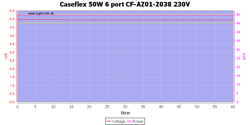
Running at 10A output for one hour was not a problem and the meter did show 10.0A both at the start and the finish.
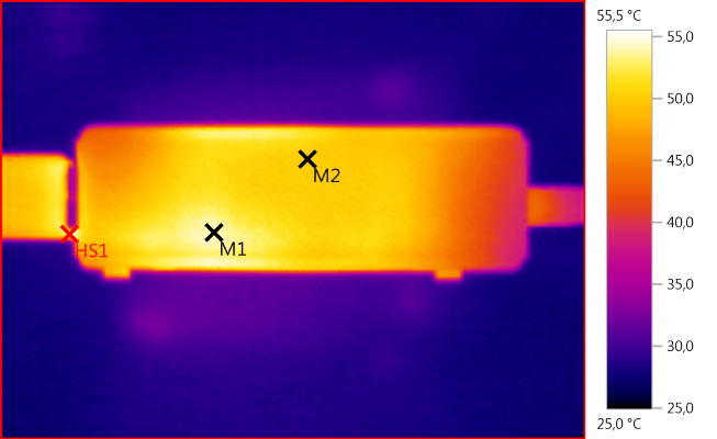
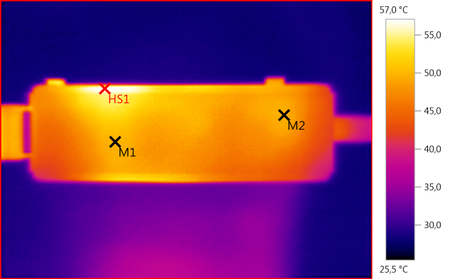
The temperature photos below are taken between 30 minutes and 60 minutes into the one hour test.
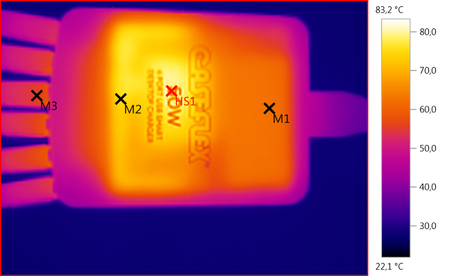
M1: 62,4°C, M2: 75,0°C, M3: 55,6°C, HS1: 83,2°C
On this photo it is fairly easy identifying the two heatsinks and the transformer inside the charger.
M1: 54,2°C, M2: 50,2°C, HS1: 55,5°C
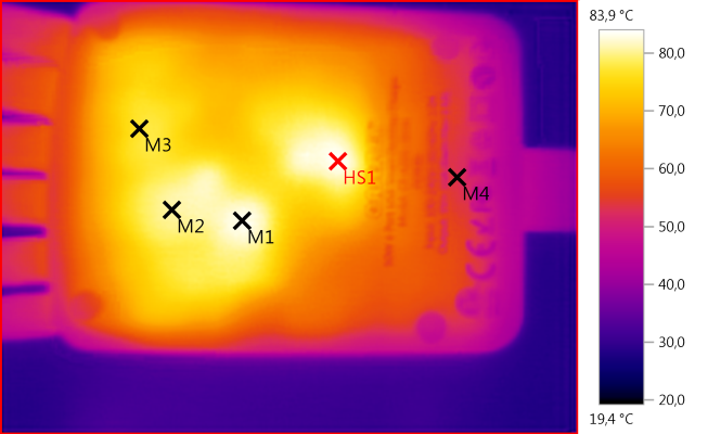
M1: 83,1°C, M2: 80,6°C, M3: 77,1°C, M4: 53,1°C, HS1: 83,9°C
M1: 49,8°C, M2: 49,5°C, HS1: 57,0°C
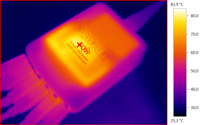
HS1: 83,9°C
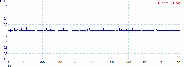
Noise at 0.5A load is: 15mV rms and 650mVpp.
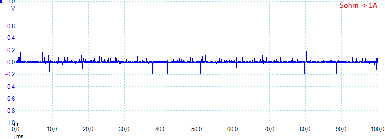
Noise at 1A load is: 16mV rms and 719mVpp.
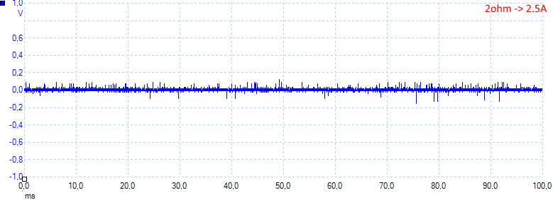
Noise at 2.5A load is: 17mV rms and 320mVpp.
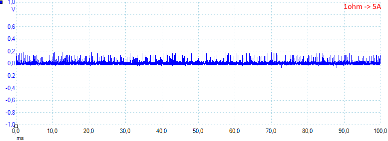
Noise at 5A load is: 33mV rms and 335mVpp.
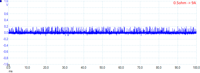
Noise at full load is: 36mV rms and 353mVpp.
Tear down
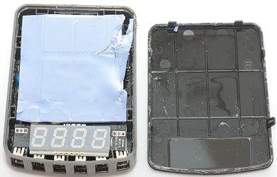
With a vice and a screwdriver I could break the top off. Between the electronic and the box is a blue heat transfer mat. This mat will transfer heat considerable better than air, making the box hotter, this means it will dissipate more heat and keep the interior cooler.
The mat can just be taken out.
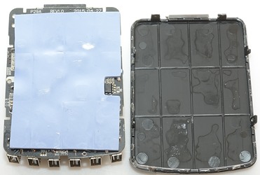
The bottom is made the same way.
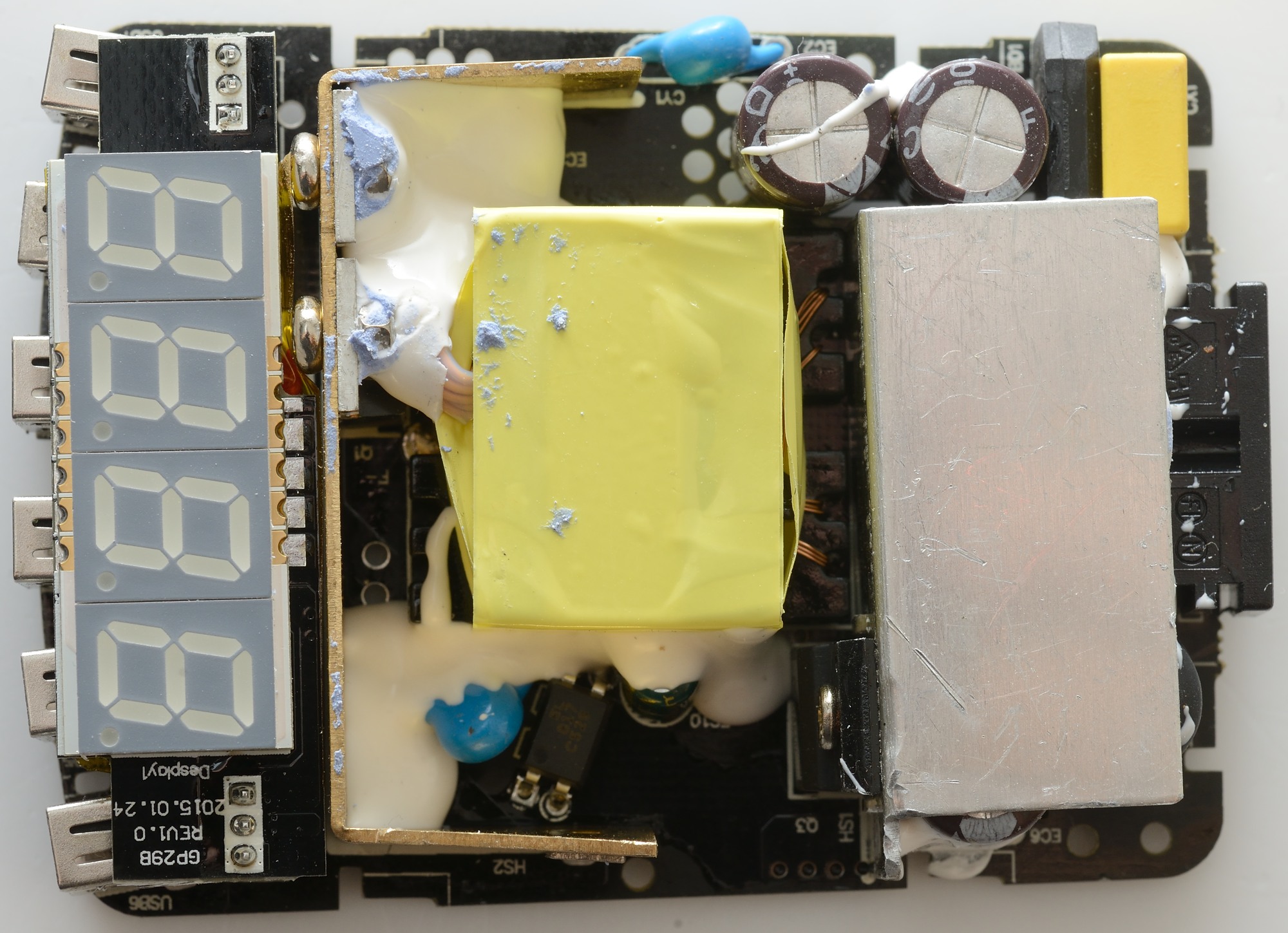
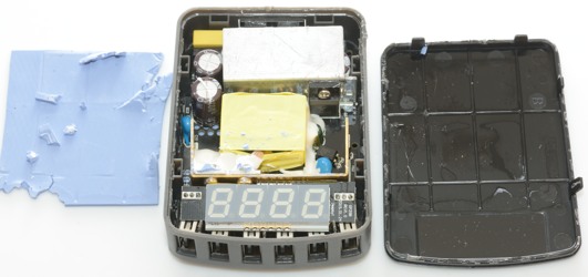
Some parts are hidden beneath the display, heatsink and the white stuff, but what can be seen is:
Just above the mains input is a capacitor, a bridge rectifier and the blue safety capacitor. On the golden heatsink is two rectifier transistors.
Below the transformer are the mains switching transistor, the opto coupler and another safety capacitor.

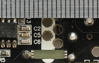
There is not much stuff under the display. 3 smoothing capacitors and the current shunt (The wire link) that is used for the current display.
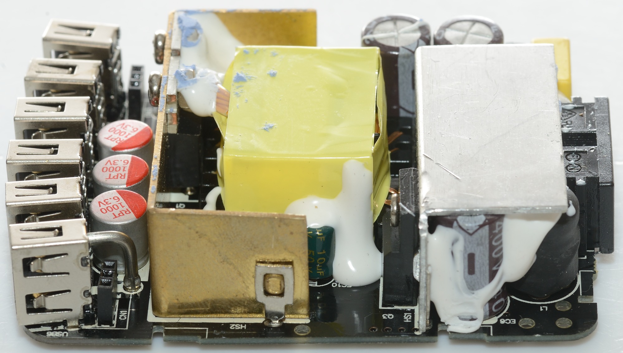
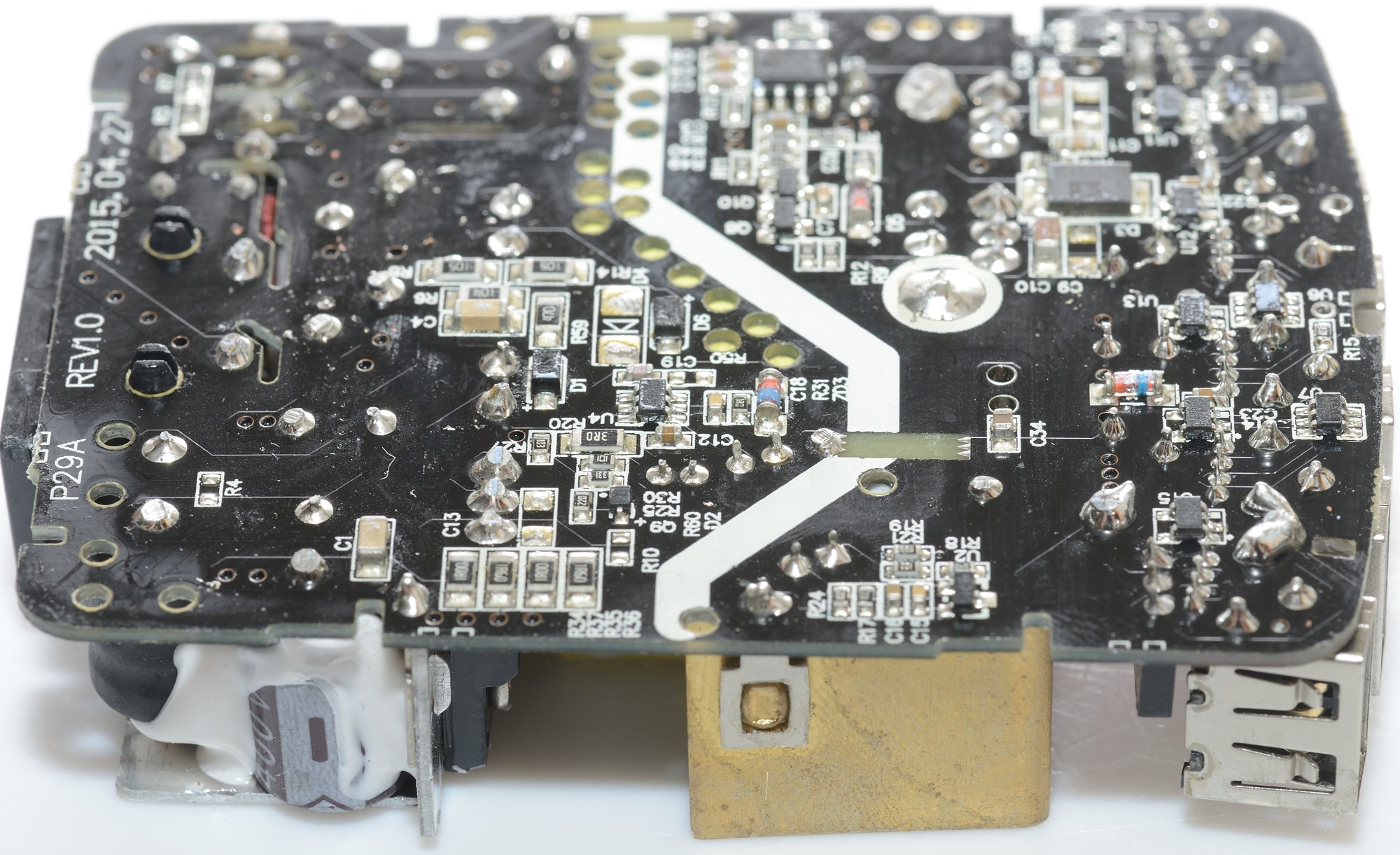
From this side it is possible to see an inductor (L1) close to the mains input connector. The mains switcher transistor and the current shunt is also easy to see.
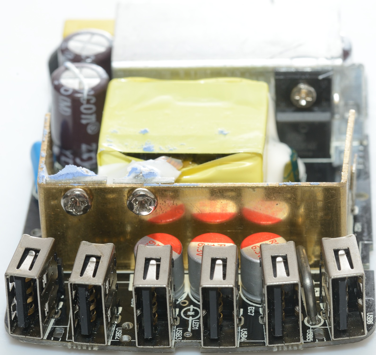
The current shunt can be seen between the usb connectors, it must not touch them. That would give wrong current measurement.
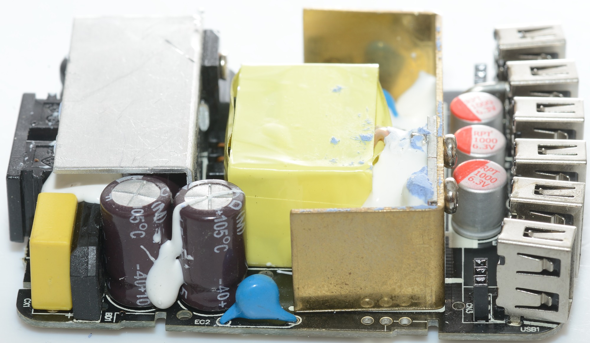
From this side the rectifier, the safety capacitor can be seen.
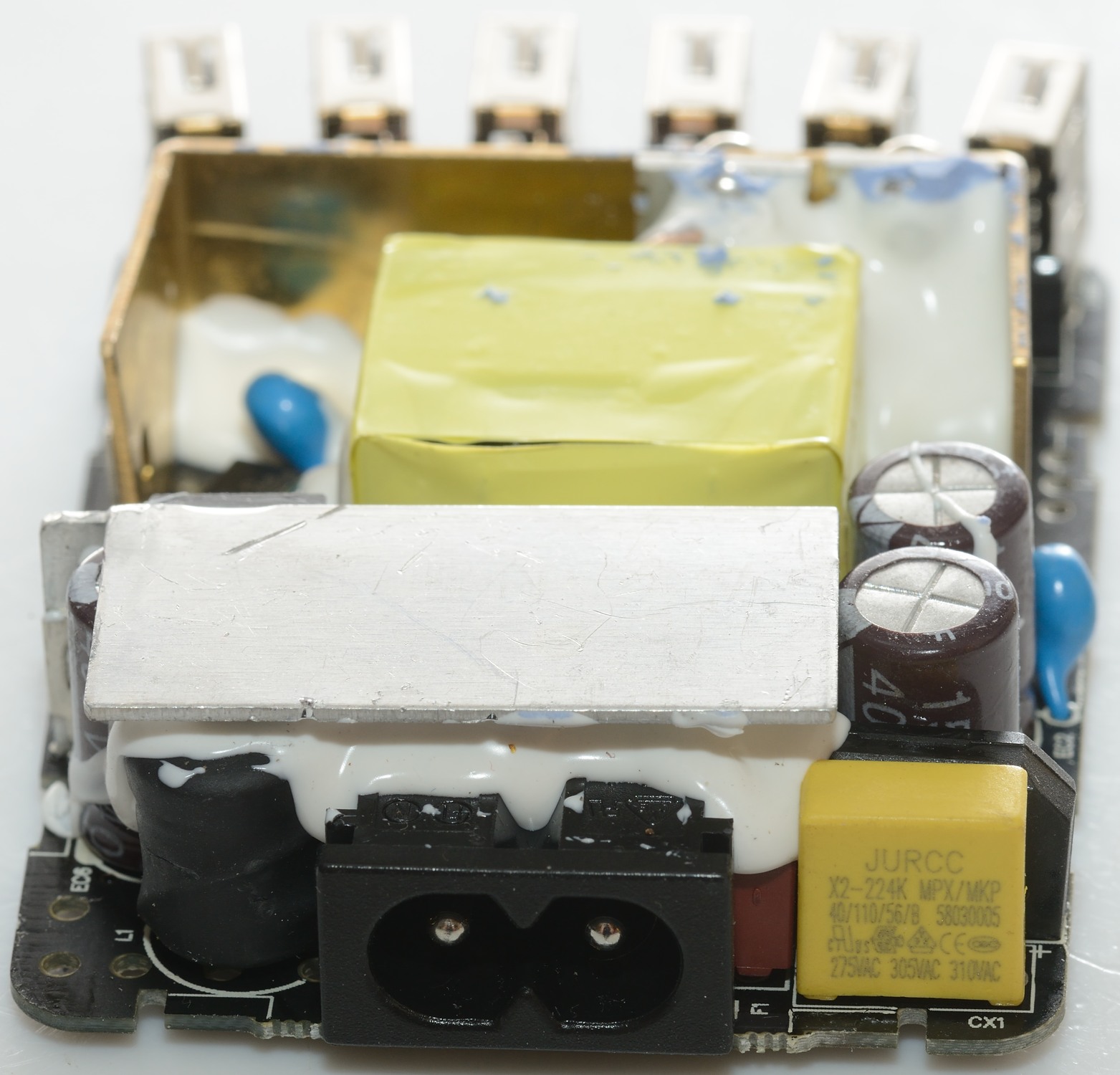
The inductor can also be seen from here and between the mains input socket and the capacitor a red fuse can be seen.
But I did not find any common mode coil, under the silver heatsink is only capacitors.

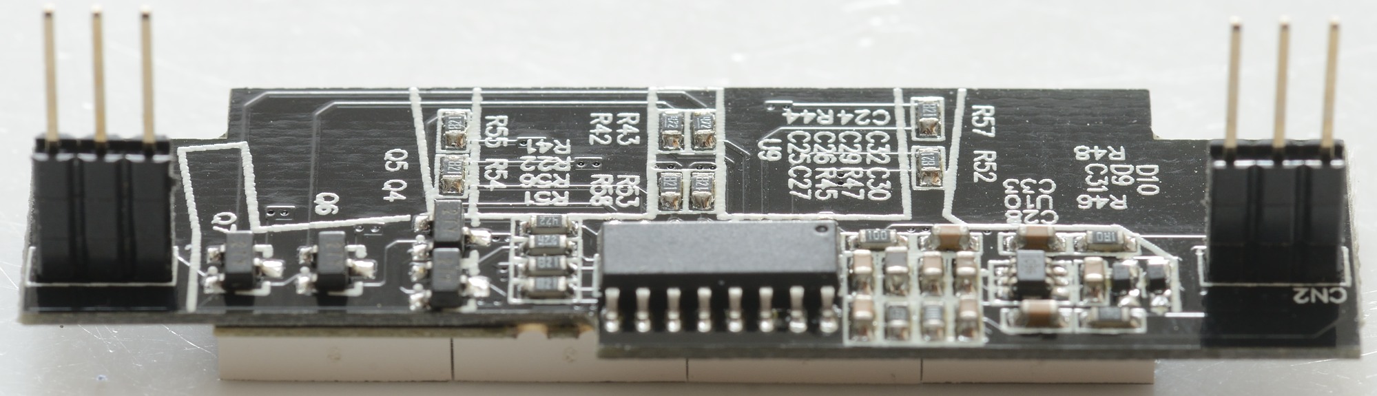
On the mains side there is a small switcher controller IC (U4).
On the low volt side there is considerable more. The 8 pin chip (U1: SP6018) is the synchronous rectifier controller.
Near the opto coupler (on the other side) is the voltage reference (U2: TL431).
Each usb connector has a chip on the + supply (U11, U12, U13, U14, U15: TD9517), this is the individual port protection, these chips are over current limiter for usb. There is also 3 chips for auto coding the usb outputs (U6, U7, U8: D1524)
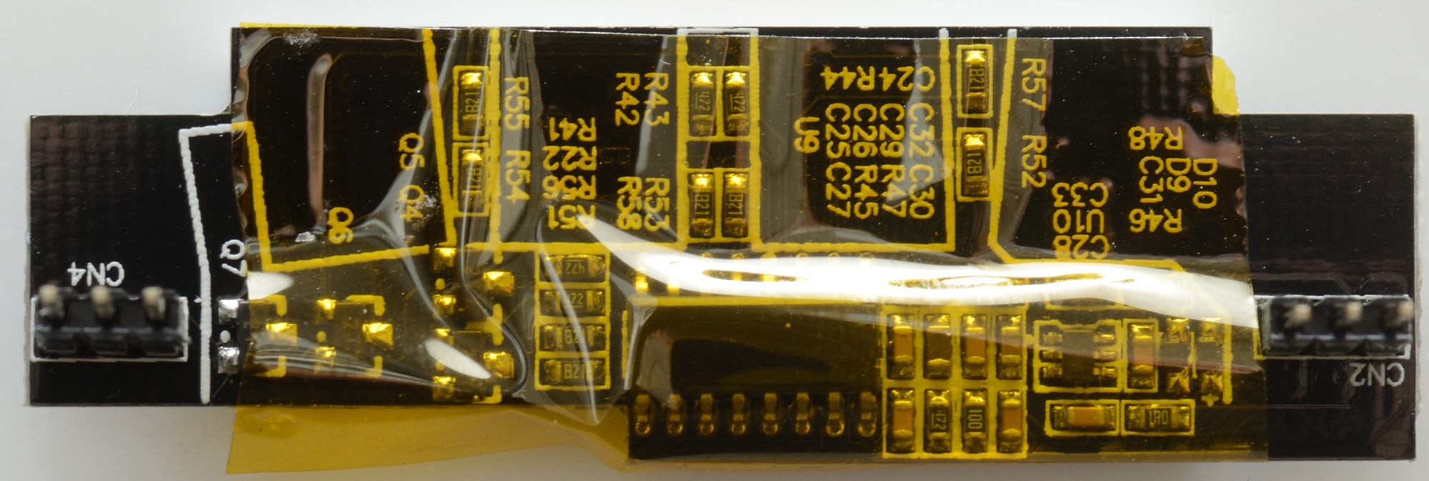
The display has com capton tape on it to avoid shorting to the usb connectors.
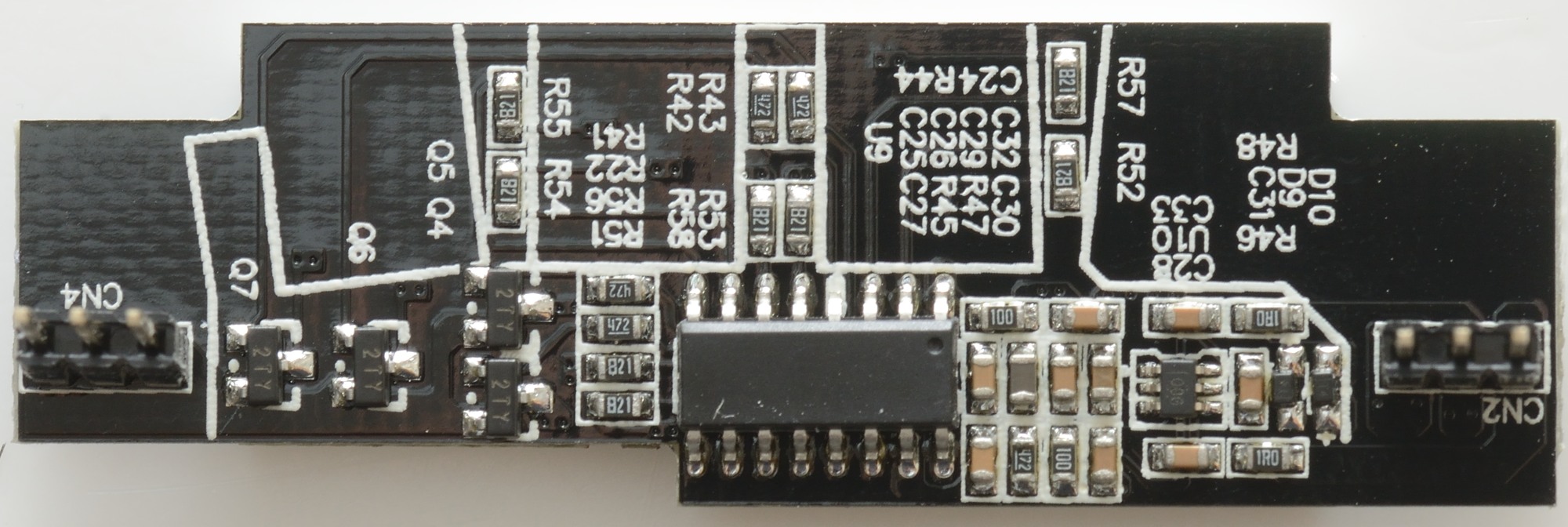
The “big” chip is either a dedicated usb voltmeter chip or a microprocessor, due to the 4 transistors I believe a microprocessor is mot likely (A dedicated chip would be able to drive the display directly). The small chip is probably a OpAmp to amplify the signal from the current shunt.
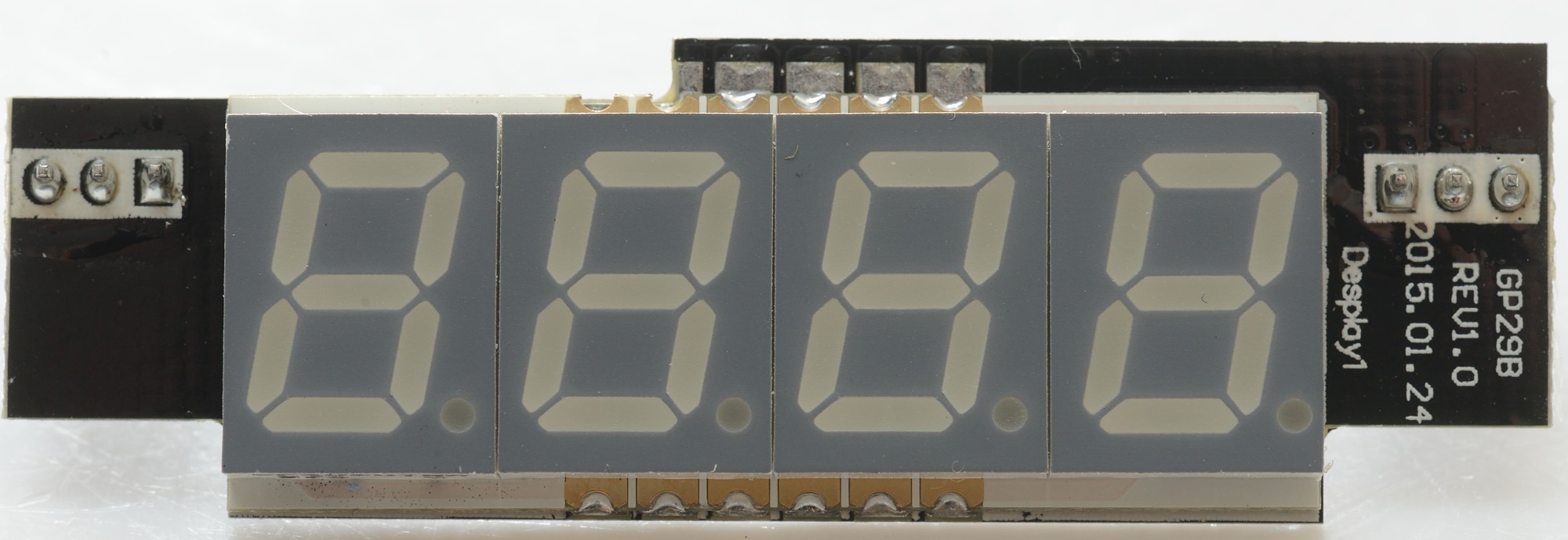
The display is a surface mount type.
It looks like there is good isolation distance.
Testing with 2830 volt and 4242 volt between mains and low volt side, did not show any safety problems.
Conclusion
Lots of output current, individual port protection, display with current, automatic coding of usb outputs, all this looks very good, but the peak noise is a bit high and I doubt it complies with EMC rules (Due to the missing common mode coil).
I will rate it as good.
Note: The build in current measurement will have much less voltage drop than a usb meter (Probably zero drop, I expect it is placed before the voltage sense circuit).
Notes
I uses a BK Precision 9801 as AC generator and switched to a variac and Tektronix PA1000 for the other curve. Future test will be done with the AC generator when possible, this makes it possible to do 120VAC 60Hz and 230VAC 50Hz and it can be done in one test run.
My high voltage test is done with a real HiPot tester allowing me to use the correct voltages for US and EU.
Index of all tested USB power supplies/chargers
Read more about how I test USB power supplies/charger
How does a usb charger work?