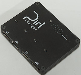
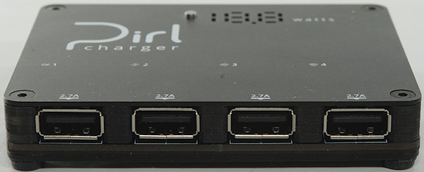
Pirl Charger 4x2.7A usb
Official specifications:
-
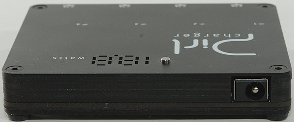
Input voltage: 7V to 17V DC
-
Output current per-port: 2.7A
-
Output current total: 10.8A
-
Output voltage: 5.05V (±0.03)
-
Output voltage increase under load: +0.15V Max (each port compensates separately)
-
Wattmeter: Resolution of 0.1W up to 10W, resolution of 1W above 10W; Accuracy ±5%
-
Measurements: 3.5” by 2.7”, height 0.6” OR 88mm by 69mm, height 14mm (without attachments)
-
Weight: 4.9 ounces or 140 grams
-
Output protection: Over-current including dead short (recovers in ~3 seconds)
-
Output data lines ESD protection: ±18-kV contact, ±25-kV air-gap
-
Input reverse-polarity protection: –18V DC
-
Input ESD protection: ±8-kV contact, ±12-kV air-gap, 400W surge
-
Thermal shutdown: All power ICs equipped with independent, internal thermal shutdown
This is a pre-release model, I got it from the developer (It is supposed to launch on Kickstarter in April 2018).
Being a prerelease model there was no box or accessories, I do not know if any will be included on Kickstarter.
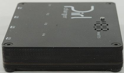
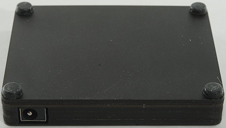
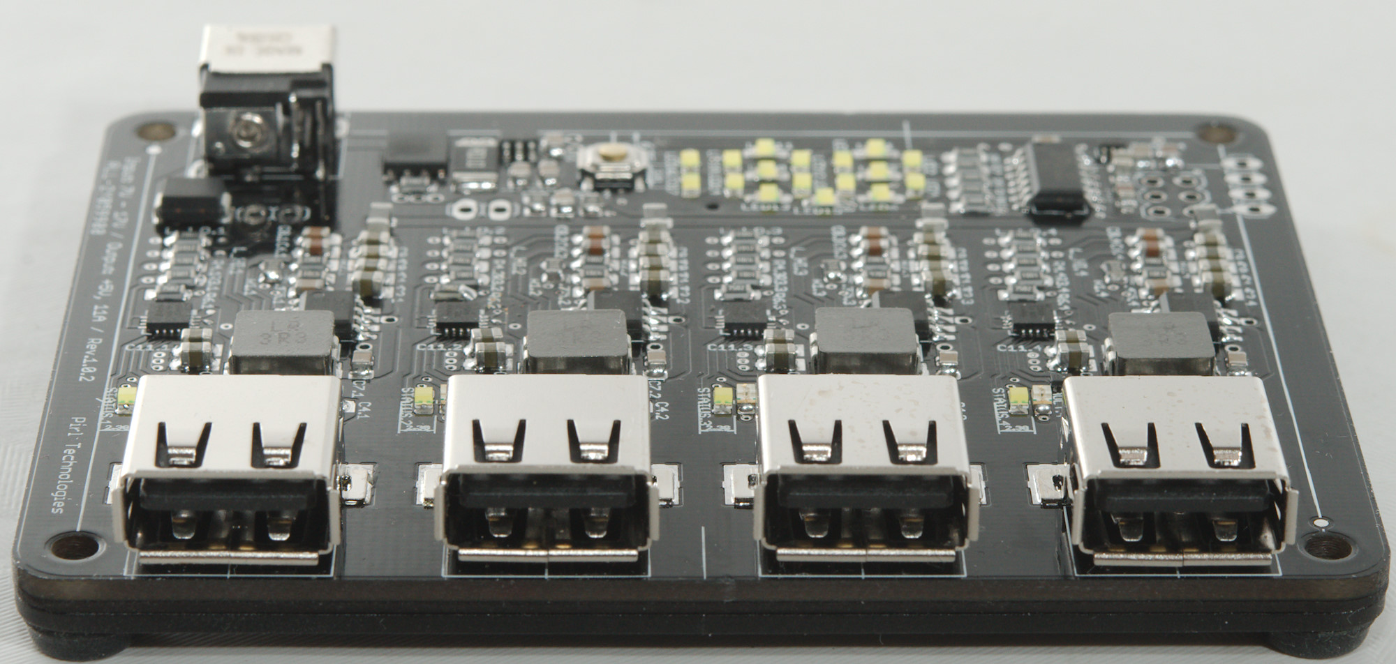
The top and bottom is aluminium.
The box is built from layers of circuit board.
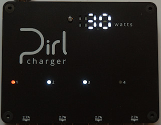
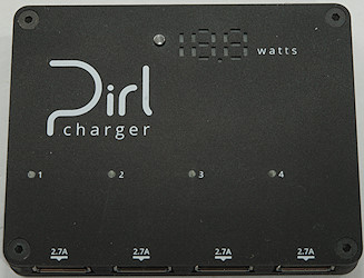
There is an indicator for each usb output, it is lit when it is delivering power and red if there is a fault.
The display shows total output power and there is a button beside it to adjust brightness of the display: off, low, medium, high.
Measurements
-
Power consumption when idle is 11mA at 7V to 21mA at 17V (0.36W) (This will be slightly lower in production version, because display will be off when unloaded).
-
USB output are auto coding with: DCP, Samsung, Apple 2.4A
-
Usb minus are in parallel.
-
Usb plus is individually regulated.
-
Output indicator turns on at about 300mA
-
Output indicator turns red when output is overloaded
-
Power display turns on at 0.5watt
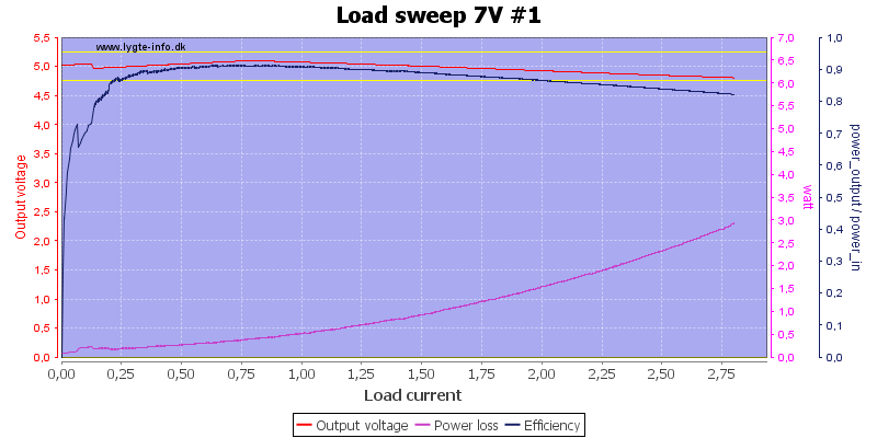
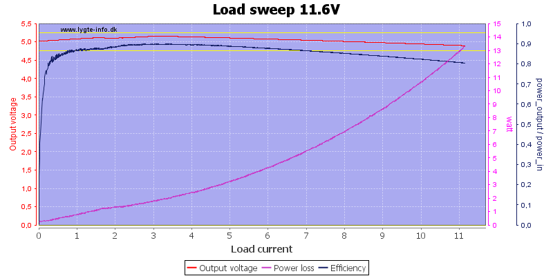
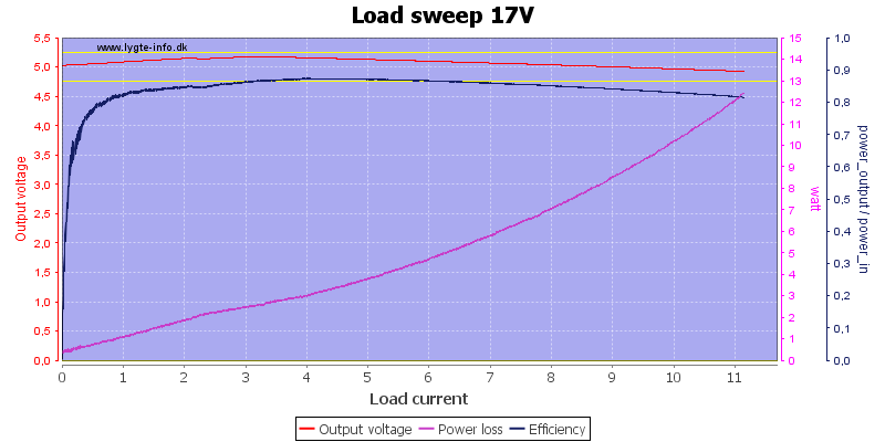
Rating is 2.7A and overload protection trips at 2.8A, this is fine. The above curve is done at minimum input voltage.
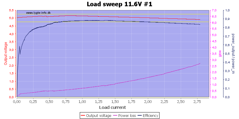
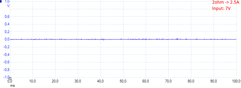
Minimum voltage in a car.
The output voltage will increase with load, but it hits maximum increase at around 0.8A, then dropping output voltage at higher current is mostly due to connection and cable resistance.
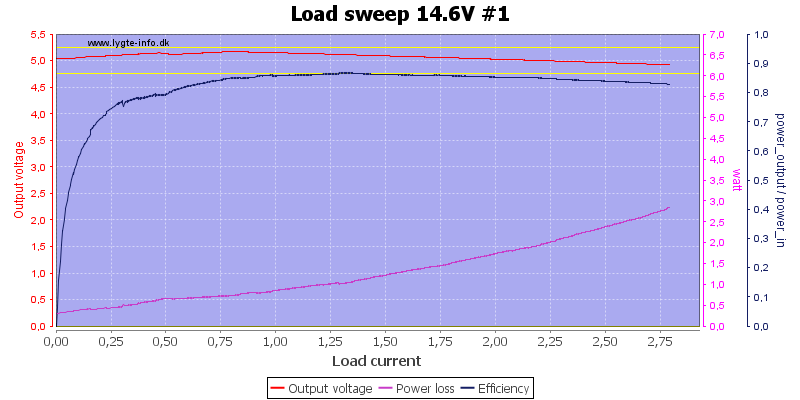
Maximum voltage in a car.
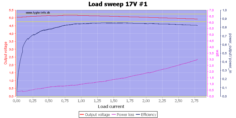
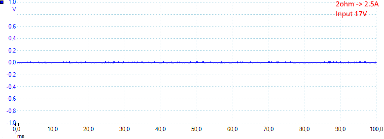
Maximum rated input voltage.
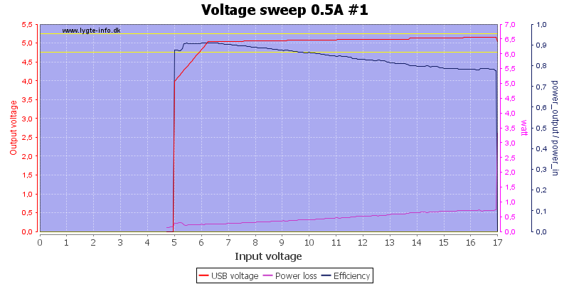
There is not much different on the output with varying input voltage.
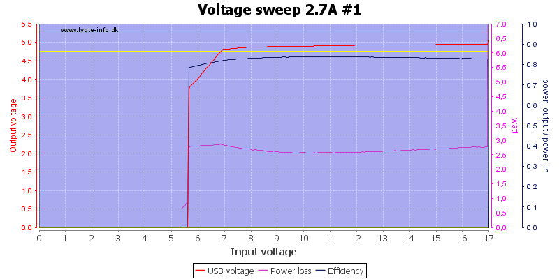
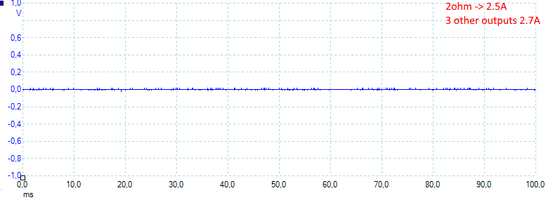
All outputs with maximum input voltage.
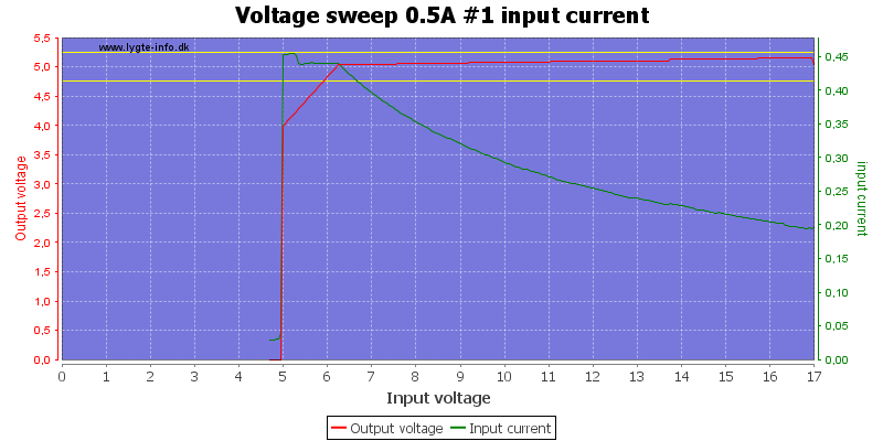
Input current will depend on input voltage, at this low load it can maintain output voltage at slightly lower than rated minimum voltage.
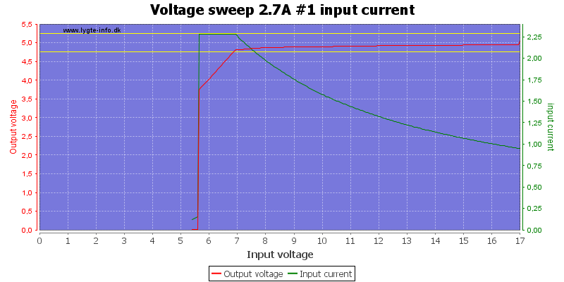
At full power it need 7V input to maintain output voltage.
Testing with all outputs at the same time.
Efficiency is slightly better than my curve shows, I have some looses in the cables and connectors.
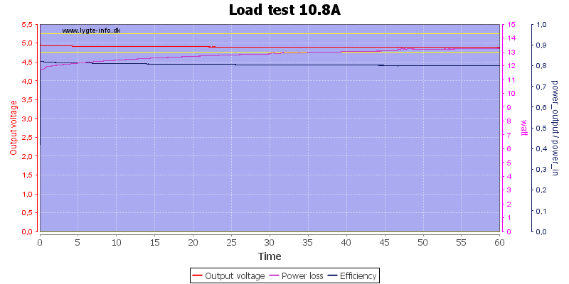
Running 1 hour at 10.8A, display on charger shows 51 Watt (It was more like 53 Watt).
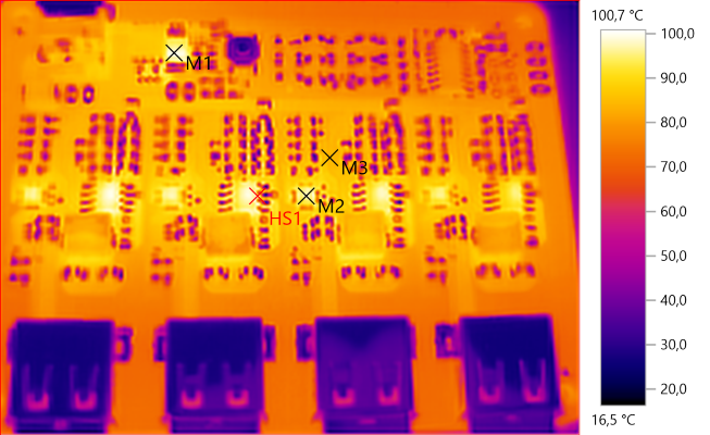
The temperature photos below are taken between 30 minutes and 60 minutes into the one hour test.
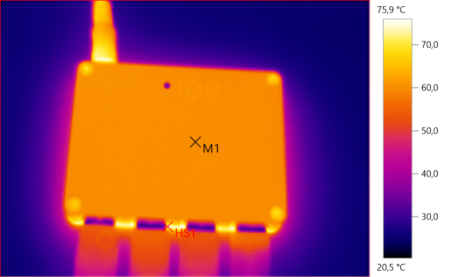
M1: 60,5°C, HS1: 75,9°C
With an aluminium top the temperature is fairly uniform, notice the input cable it is hot due to power loss in it and the connector.
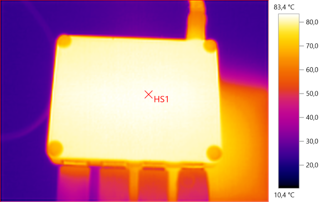
HS1: 83,4°C
At full power the bottom gets very hot (In real usage this power level will seldom or never be reached).
M1: 99,4°C, M2: 98,1°C, M3: 83,9°C, HS1: 100,7°C
After the above boring pictures, I did a test more with it open. 100°C may sound bad, but the chips are rated for 150°C inside, i.e. it is not too hot for the chips.
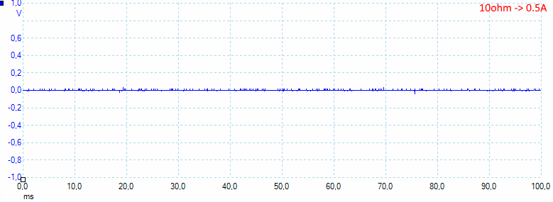
Noise is 11mV rms and 83mVpp
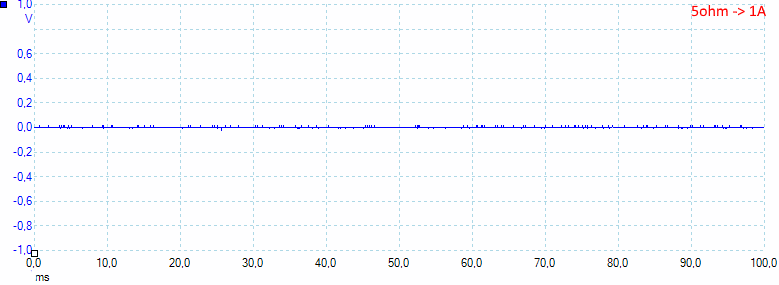
Noise is 10mV rms and 107mVpp
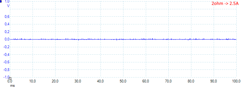
Noise is 3mV rms and 57mVpp
Noise is 3mV rms and 58mVpp
Noise is 2mV rms and 58mVpp
Noise is 8mV rms and 94mVpp, all tests show very low noise.
Tear down
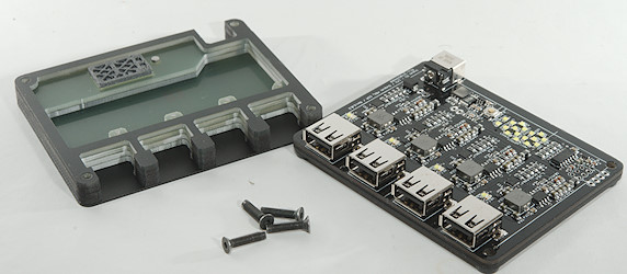
Four screws and it was open.

The top has light pipes for all the indicators.
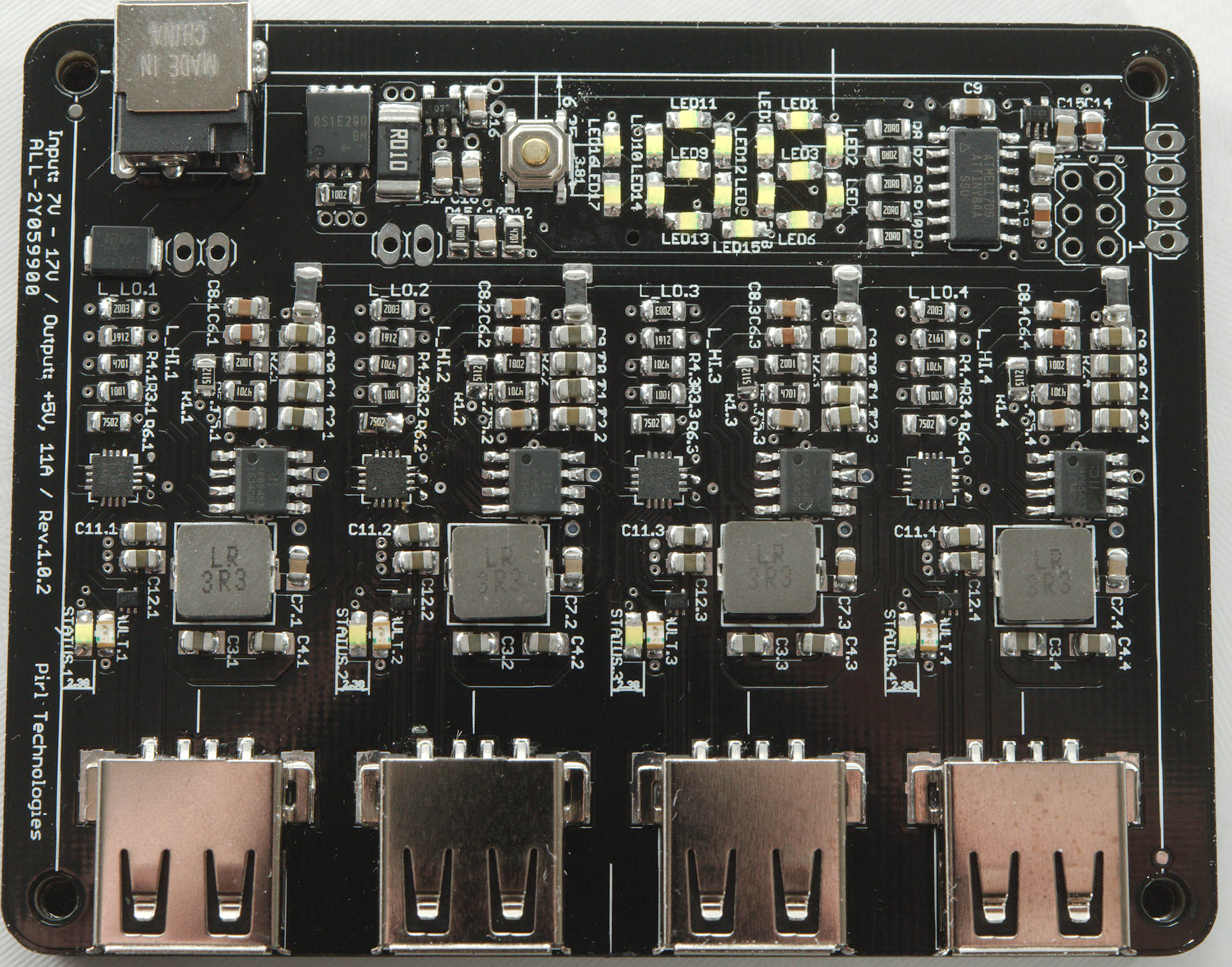
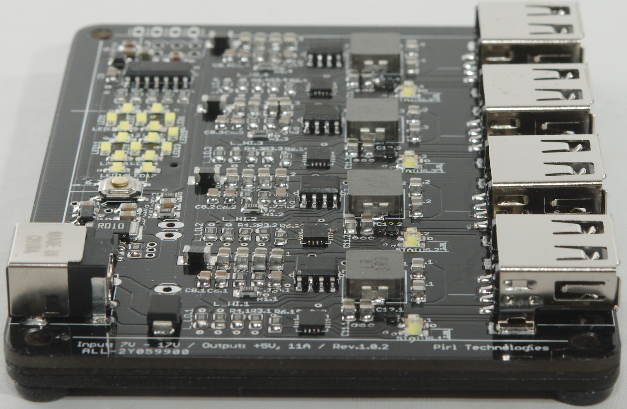
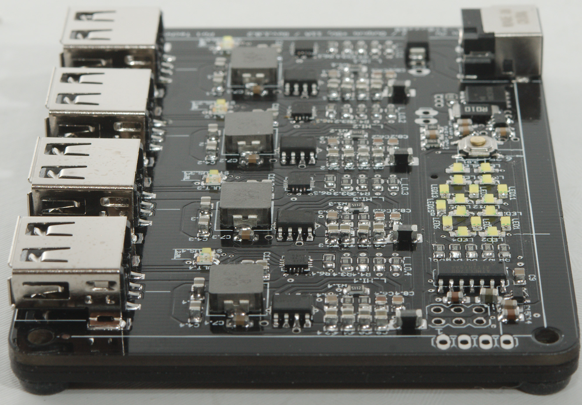
At the input is a high current power mos (RS1E200) and a sense resistor (R010) with a current sense chip (Probably ZXCT1022). For showing power is a microprocessor (ATTINY84A) with its own power supply chip (Maybe TPS715).
Each channel has a buck converter (AP65453) and a usb charge controller chip (TPS2549) that handles increasing voltage, protocol and overcurrent. The is also a small chip, I believe it is a voltage monitor (Maybe X6101 series). There is both a white and a red led for each channel (No multicolor led).
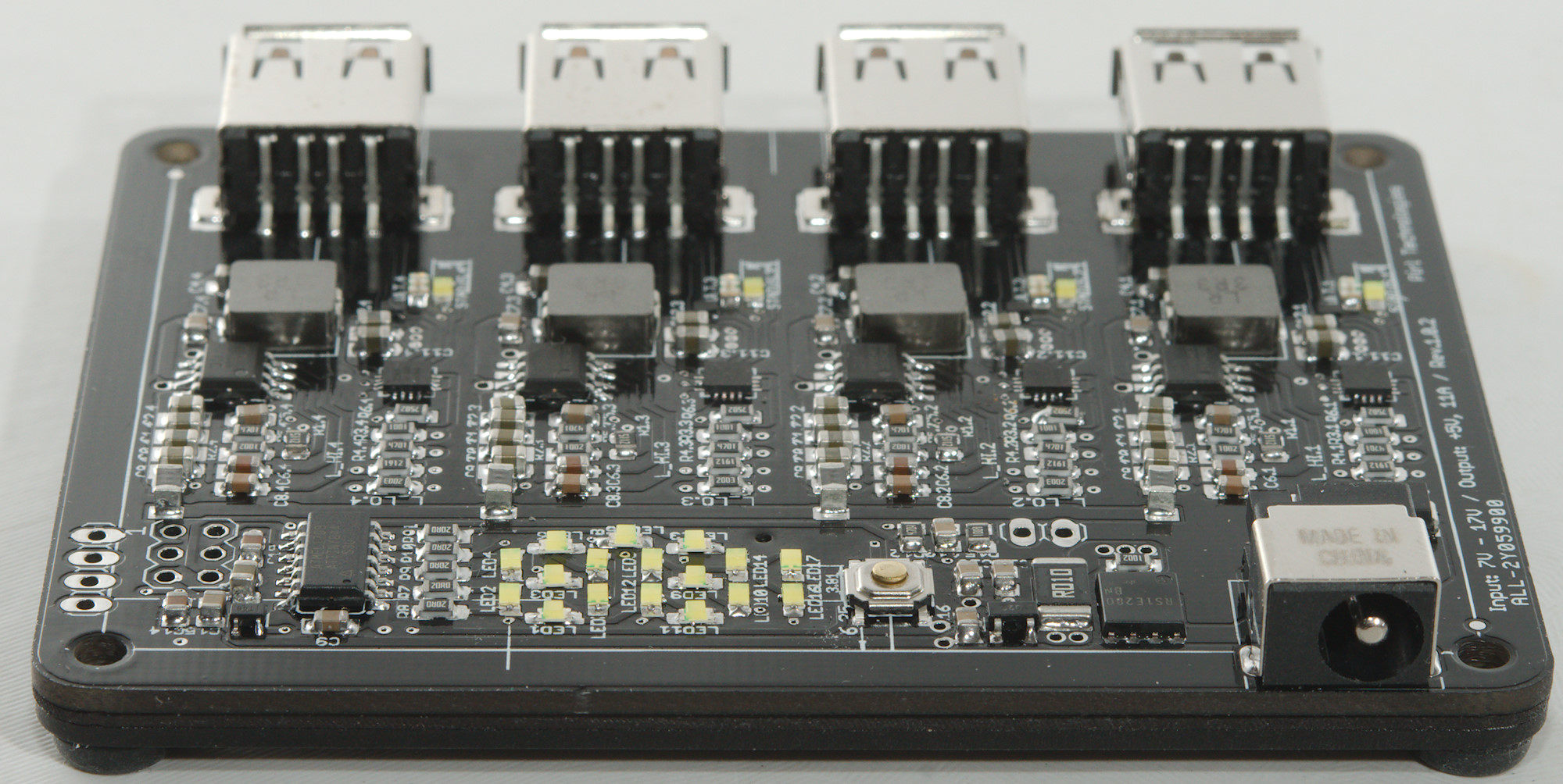
Sorry, no pictures from the bottom, the circuit board and the bottom aluminium plate would not easily part.
Conclusion
This is a very powerful usb charger, has auto coding, very low noise and individual port protection. The high temperature at full load is not really an issue, no standard usb devices will get it that hot.
I like a display showing output current or in this case output power (The processor must be doing some math with the sense resistor on the input).
The question is where to use it? In the car with a cable to the car battery, in the house with a external mains power supply (Sadly it cannot be used with a typical laptop supply).
I will rate it as a good usb charger.
Notes
The charger was supplied by pirlcharger for review.
Index of all tested USB power supplies/chargers
Read more about how I test USB power supplies/charger