Parasitic drain, parasitic load or standby power/drain, is a problem we are seeing more often with the rise in popularity of e-switch lights, and with more complex circuitry of built-in charging, AUX LED's, etc. It can come from the design (firmware or choosing circuits or components that tend to "leak") or quality issues such as bad or leaky components, or partial shorts.
I received this ROT66 Gen II from a fellow BLFer to do a tear down of, since it has been killing sets of batteries. So besides the tear down, my goal was to find the cause and fix the standby drain problem.
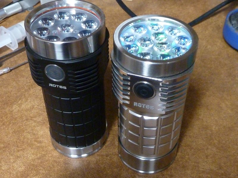
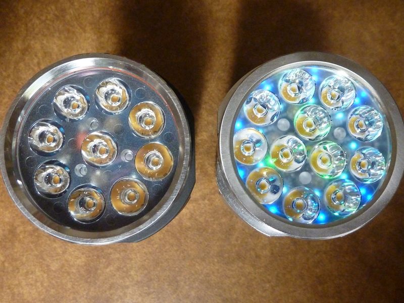
Here's the raw Gen II with my old 1st gen ROT66 (9 LED). Overall improved with more LED's, AUX LED board, smaller size, bigger SS tailcap, battery carrier eliminated, and grippier tube:
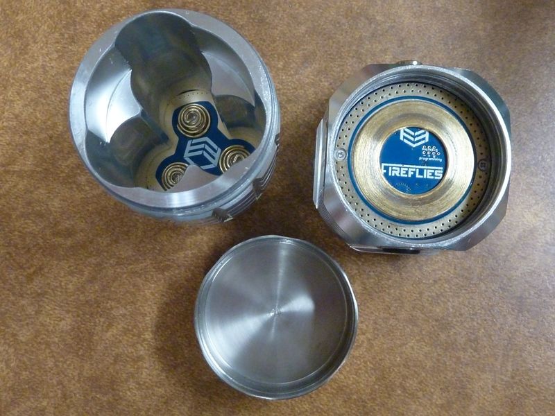
The housing is impressive:
Easy to remove the bezel and optics:
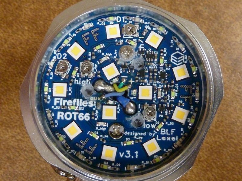
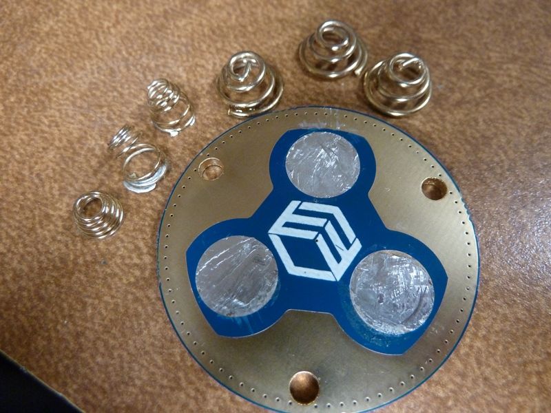
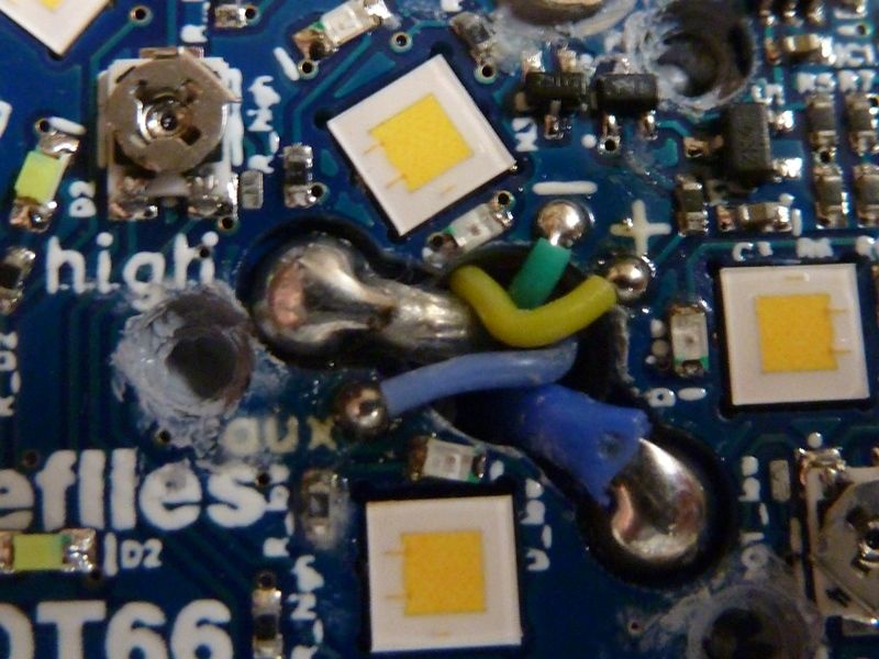
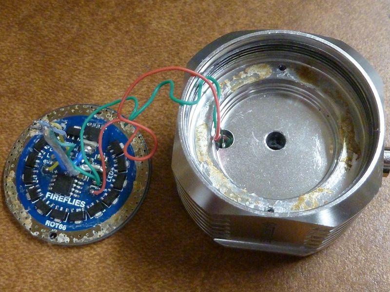
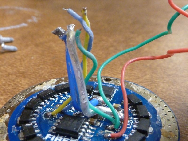
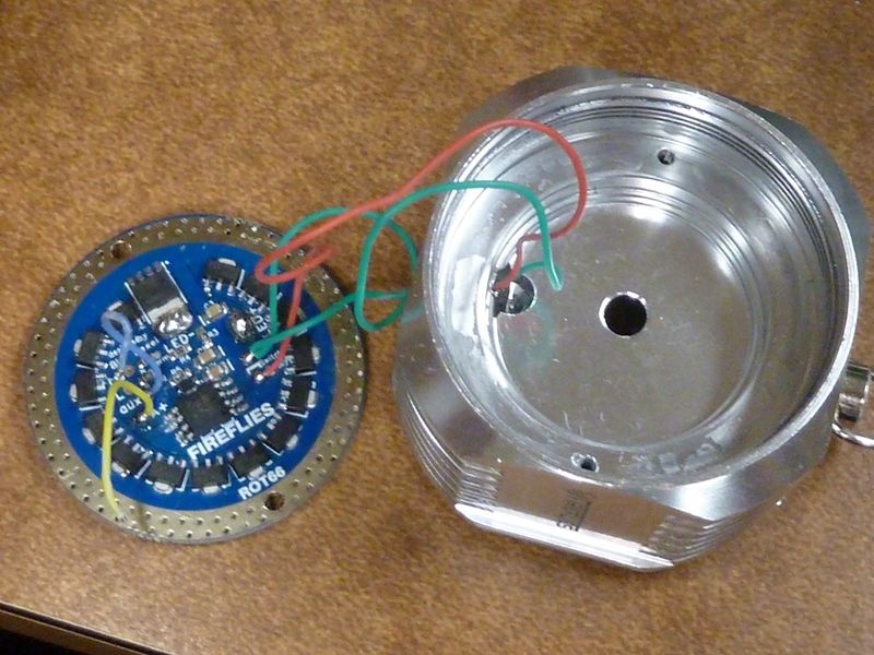
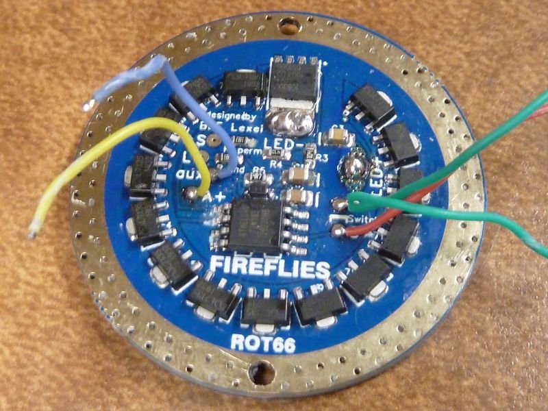
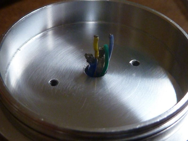
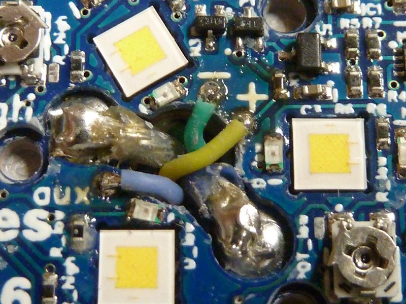
You can tell teflon coated LED wires are used here to get the lowest resistance for the given thickness. I don't like working with teflon coated wires because the strand size is much thicker and therefore the wires are stiff and more difficult to work with. If not handled properly, they can easily rip pads off of board because of the force you need to apply to bend/shape them. The 3 small wires (30 AWG) are ground (green), Batt+ (yellow) and AUX/switch output (blue) that is firmware controlled. Since al the LED's are controlled by the firmware, I assume the Batt+ is there in order for this AUX board circuit to monitor the batteries for LVP. The lights will turn down, and eventually go off as the batteries drain to low levels.
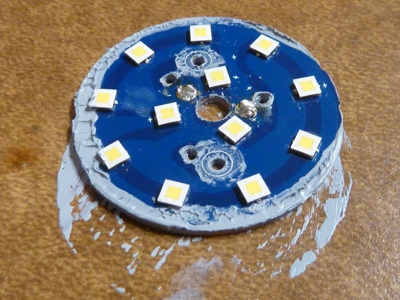
Removed the AUX LED board and noticed they got real sloppy with the thermal grease - what were they thinking here?
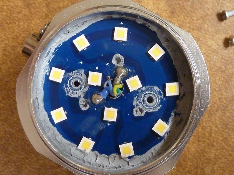
Removing the MCPCB, this is a mess. To get the teflon wires off, I decided to go with using solder wick with a decent amount of flux to remove as most solder as I could - worked out well:
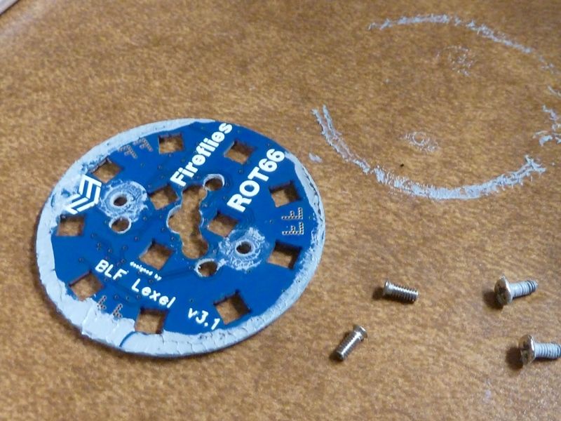
Removing the driver was a little challenging. It seemed easy because of 2 small screws holding it down in pace, but for some reason they used a large amount of glue all around the driver as well:
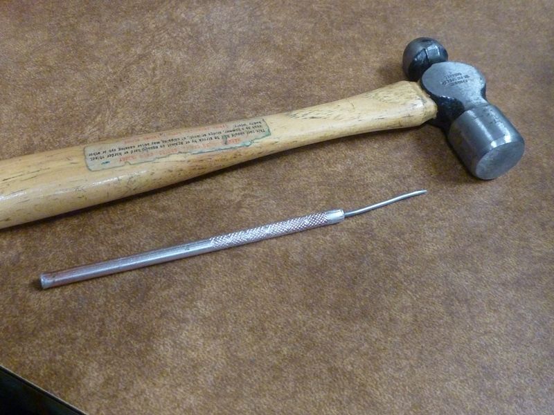
I was able to fit a solder pick tool down the middle hole and it took a few taps to loosen it up, here's the tools:
The amount of glue used was ridiculous:
The problem is using this method is the risk of damage to the driver. In this case, I knocked off the small diode that's there for polarity reverse protection, but fortunately the board and pads were undamaged, so easy to replace it, part marked 41 just above the MCU:
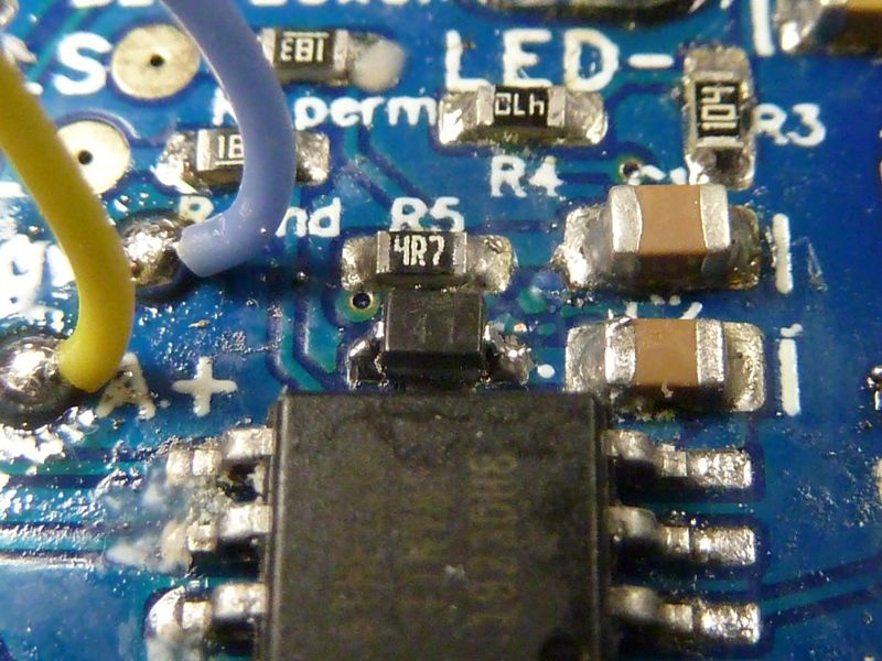
Close up of the driver and stock wires. Weird teflon coated wire colors of blue for LED- and clear for LED+:
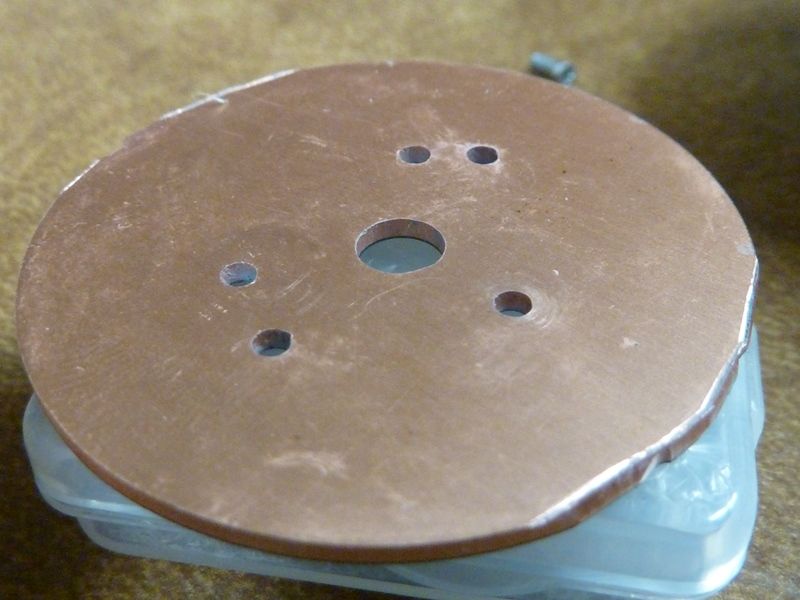
Looking closely at the MCPCB, I see they left burrs on two spots of the edges, where the tabs from manufacturing were. There were also burrs from the screw holes on the shelf the MCPCB sits on (not shown):
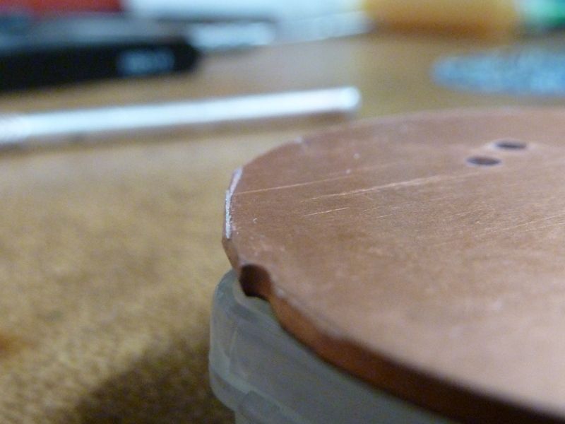
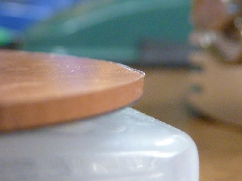
Sanded them down so it's all flat and smooth now:
After removing the glue as much as I could:
While I got the driver exposed, good time to upgrade it to the latest Anduril 2 I have, so flashed A2 at this point.
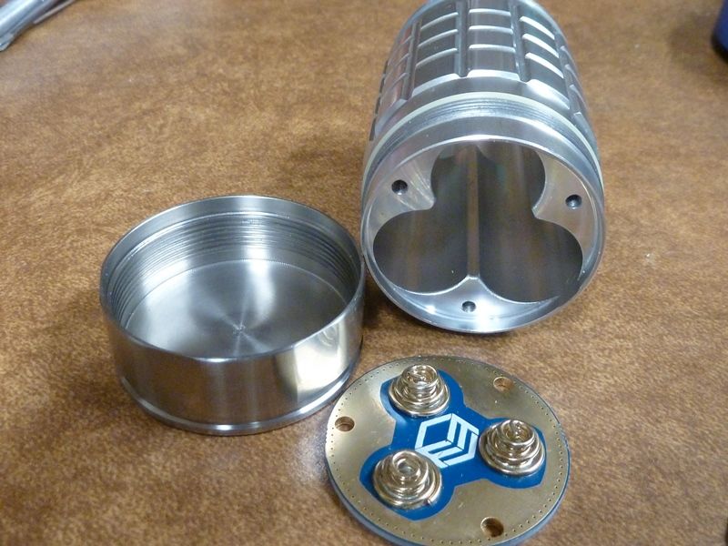
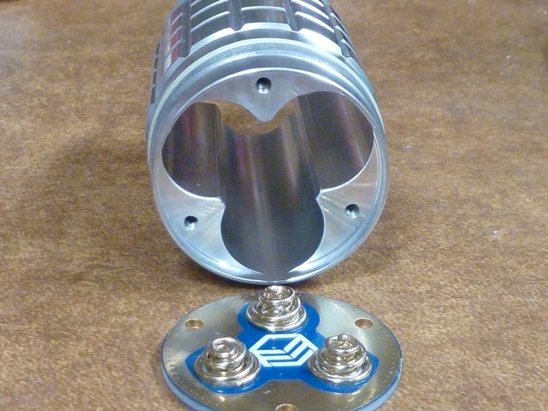
The quality of the overall flashlight housing is impressive! Not sure how much is related to the 7075 grade aluminum, but it feels very solid, and even though this light is used and passed through two prior owners, there's not a noticeable scratch or mark! For the tail springs, I'm not a fan of this type of dual spring design. They don't appear to be high quality spring, and the inner springs are so tiny, they can't be helping much.
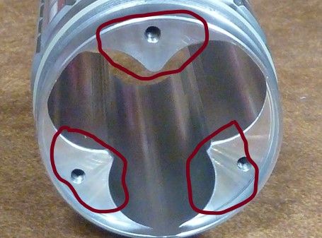
The bottom tail contact surface is proper raw aluminum, no anodizing, for surfaces marked here:
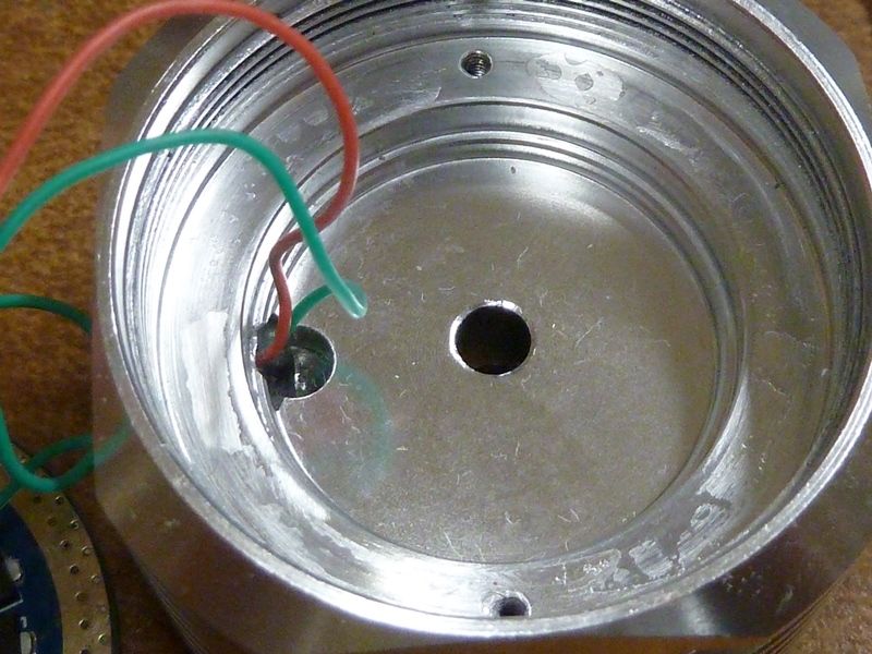
However on the top contact surface, the surface that contacts the ground ring of the driver, it is anodized! Why would they do this? It had to be a mistake.
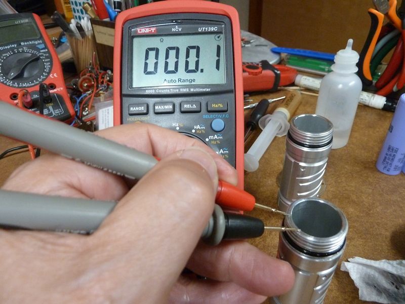
Tp check it, just do a simple continuity check. A WT3M tube here is used as a reference, and the meter shows continuity:
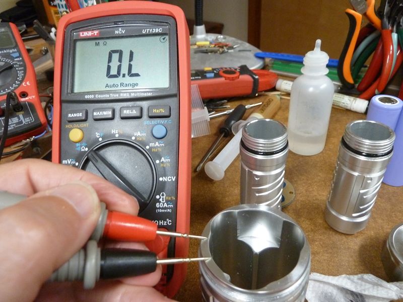
For the ROT66, there's no continuity:
So I sanded down the top surface, using a strip of 600 GRIT flat down on the table, them sliding the tube across it, and now most of the contact surface shows continuity now:
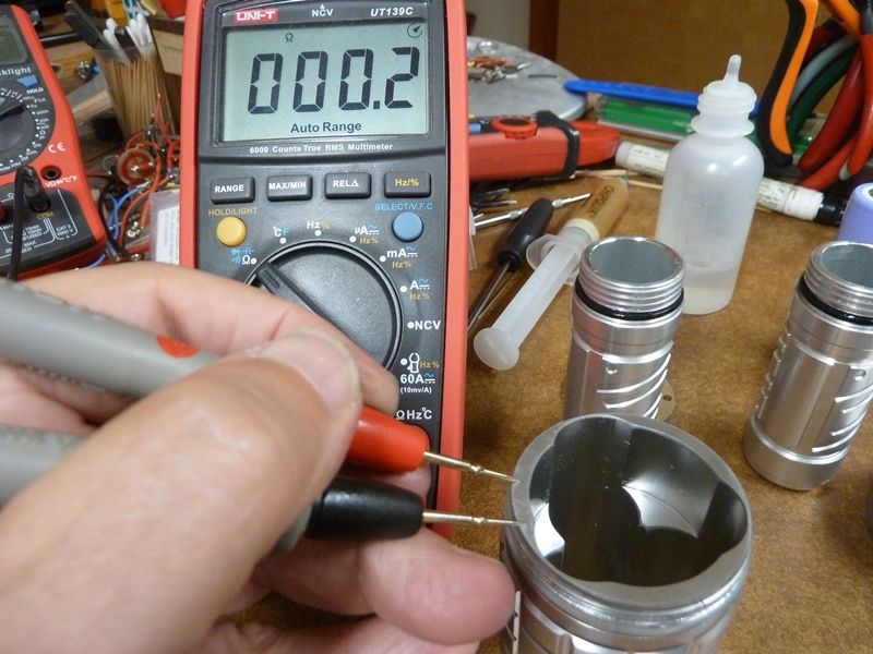
The surface wasn't completely flat, so the anodizing wasn't completely removed, but at least 3/4's of it was removed, should be good enough.
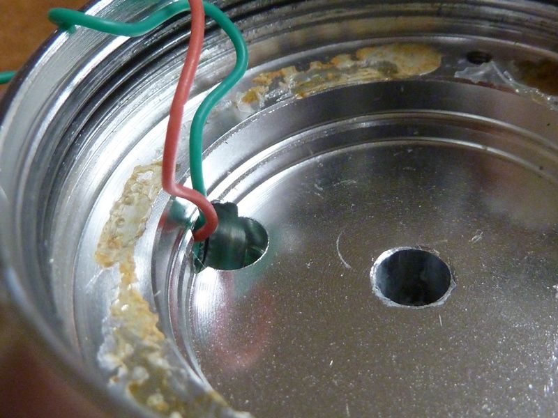
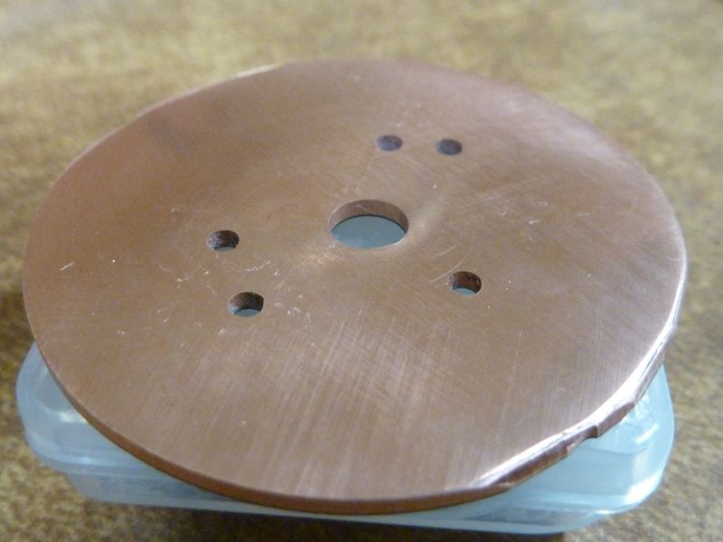
Re-installing the driver, got to get those 5 wires back in position. Notice the de-burring - the center hole was factory deburred, but I deburred the two screw holes, and polished the surface with up to 3000 GRIT padding/paper:
All the wires re-soldered:
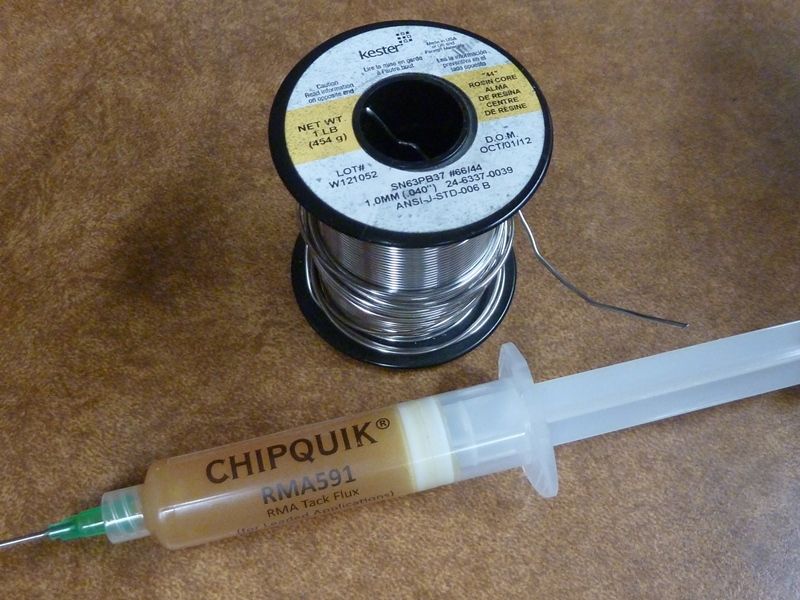
Some supplied used - favorite solder for the iron, and flux:
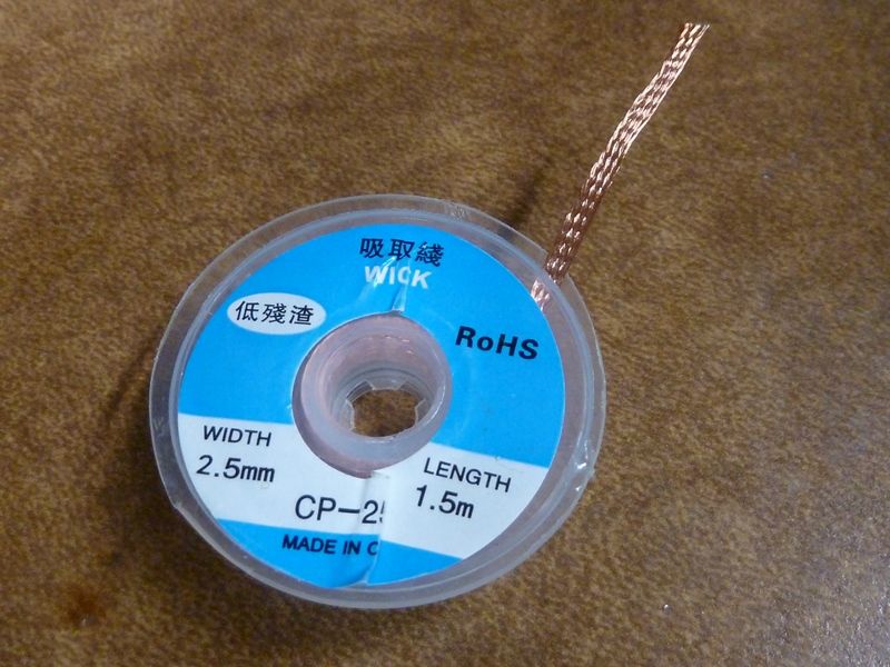
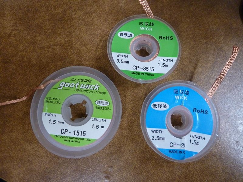
Solder wick used, and assortment I keep handy in different sizes:
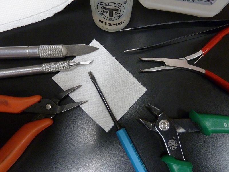
Some common tools used for this tear down:
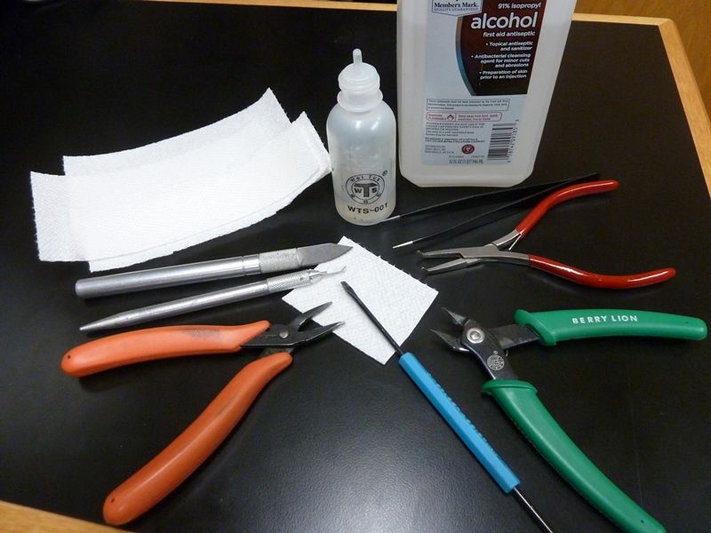
Closer look. 91% alcohol with a small easy to use dispenser. The sharp blades come in handy, including scraping off glue, etc. The red handled needle nose on the left are my general purpose pliers used often for many things - the tips have rounded backs that come in handy for many switch bezels. The blue handle tool is also nice for scraping. The cutters for wiring. The red needle nose on the right work well for holding down wire ends for soldering, and finally the tweezers.
Results
When I received the light:
- measured 5000 µA (5 mA) as-is
- reduced to 2800 µA (2.8 mA) with brightness adjustments turned down
- with all the AUX LED's off via the UI, 2300 µA measured
After the tear down, cleanups and re-assembly:
- driver by itself without the AUX LED assembly connected: 34 µA
- on high, all AUX LED's on: 673 µA
- on low, green LED's only: 128 µA
- with all AUX LED's off via the UI: 94 µA
Conclusion
There were a few discovered issues with this light:
- sloppy, excessive use of the thermal grease
- unnecessary and excessive glue holding the driver in place (already had 2 screws securing it)
- poor electrical contact from the battery tube to the driver ground
- burrs in the critical thermal contact area of the MCPCB to the shelf
Clearly, the results show the parasitic drain has been significantly reduced.
When I first got the light, my suspicions were a leaky part on the driver, like the FET or a 7135 - that didn't end up being the problem. From the issues found, the only one I could think may cause the excessive drain (2300 µA down to 94 µA) is the sloppy thermal grease, though it's typically not electrically conductive, but this is stated on the Arctic Silver 5 listing on their website:
Not Electrically Conductive:
Arctic Silver 5 was formulated to conduct heat, not electricity.
(While much safer than electrically conductive silver and copper greases, Arctic Silver 5 should be kept away from electrical traces, pins, and leads. While it is not electrically conductive, the compound is very slightly capacitive and could potentially cause problems if it bridges two close-proximity electrical paths.)
So it could be the cleanup of the grease, or some other contaminant that got removed in the cleanup process.
Performance:
on 3 VTC6 solder top cells at 4.20V, lumens: 7575 at start, 6420 at 10 secs, 6210 at 30 secs
This was on the light in stock condition. I'll be bypassing the springs and trying better cells. The LEDs are XPL-HI 4000K, I assume 5D's. I would have expected closer to 10,000+ lumens as rated, but on only 3 cells, and only one pair of LED wires that can't be increased in size, maybe that's all it can do.
Stock springs - guess the outer ones are decent, but the inside ones look too thin to do much: