Hi
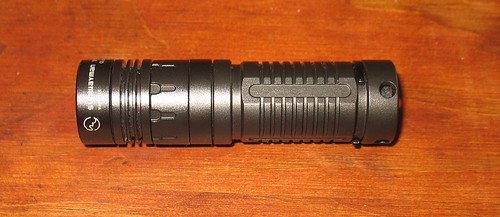
I bought myself a Sunwayman V10R, and it’s fantastic. I knew when I bought it that I would not be happy with the cold blue LED, and would have to try an emitter swap.
I don’t know why manufacturers insist on using them - any emitter swap mod you ever see on here or CPF is always cold -> warm, never the other way!
I had read all the horror stories about how to take the head apart, so I was prepared for a battle - but I discovered a little trick that made it a piece of cake….
Start with a V10R, the best little EDC a man could hope for…
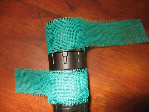
Now, to remove the head, I wrapped the two parts in jewellers finger tape - a special kind of tape that you wrap your fingers in to keep them clean when polishing jewellery.
I intended to use this to protect the two halves of the head from the vice grips, ’cos I’m too lazy to make a proper clamp, as shown in previous how-to posts.
As luck would have it, vice grips were not needed - I just dismantled it by hand!
Note that the tape is wrapped from different directions, so that as you apply twist to undo the head, it tightens the tape. I left the battery tube in during this time, to prevent crushing the head threads.
So now the head is out, the little plastic centering spacer can be lifted out.
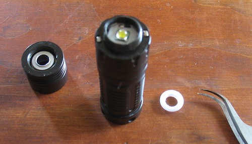
The horrible blue LED can now be unsoldered and lifted out. It is not held in by anything.
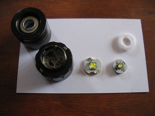
A new XPG CRI90 LED module is put in (with some new heatsink compound), and soldered. I tinned both the wires and the pads with proper lead-based solder, for easier soldering. I have never soldered to a metal PCB before - I was quite amazed at how much heat it needed!
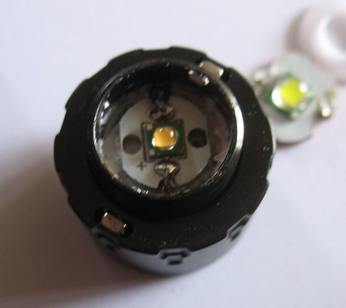
It is not held centered by anything other than the tension on the wires. If I were to do it again (or just improve this one…) I would hold it in place with a drop of Arctic Alumina cement, which I have heard of, but never used. As the new PCB is a lot thicker than the old one, I had to leave the spacer out. I was worried that without the spacer pressing the PCB down, heat transfer would be affected. It doesn’t really seem to be a problem, though. Cement would also help hold it nicely centered.
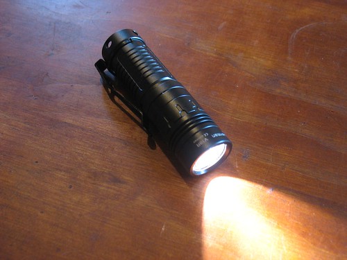
There it is, all ready to go! Behind the tail of the flashlight you can see the blue cloudy-day light from the window - compare that to the nice warm of the XPG!
I’m sure the total light out is reduced, but I don’t mind - this is my EDC for looking behind computers and under desks, so the output is plenty for that!
I’m super happy with my first mod - now the flashlight really feels ‘mine’, customized to suit me better than any of the other V10s would.
Thanks for reading, hope it helps someone!
Pete
