It was, for a brief moment, the Z8-RGB, but alas: I scr***d the green led  . This is how it went:
I always wanted the Quark RGB but it was sold out as soon as I became aware of its existence. But since a few weeks intl-outdoor offers the MCE-color led (the white is neutral) on 20mm mcpcb and moreover: a 20mm driver to go with it. Not cheap: it took me a week to decide to order  . The driver has a rather primitive UI (i.e. no colour mixing) but it does a job at driving the mce.The current coming out of the driver is 700mA for all colours, but only one at a time (a real pity: no colour mixing, but then: it would be a very clever UI to have any user friendliness and at the same time mixing features, using just one button). The driver and led-board being 20mm, it is meant to be build into a fat 18650 body, but the modest current of 700mA screams for a small 14500 light. What to do? The solution: pull out the electric sander and make it fit
  .
.
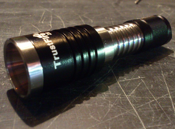
I thought the Trustfire z8 would be a great host: having a zooming feature that the Quarck never had (it is said to be very floody). I did some measurements on Johnny Macs pictures from his review (thanks a lot JM for some excellent macro-pictures  ), and figured that with a lot of sanding and a narrow squeeze it would just fit. I ordered the Z8. And here it is.
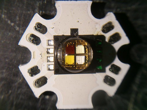
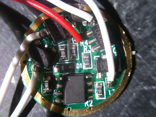
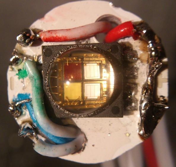
And here are the led and the driver:
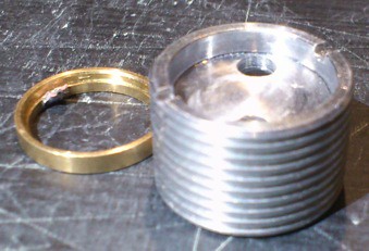
I took out the pill of the z8, it appeared the driver had a brass containment ring around it, that certainly had to go, and the new driver would never fit inside the pill so it had to sit under it, that way just one mm had to be sanded off. Here is the pill with the old driver, and the pill with driver,led and brass ring removed, note the thick layer of aluminium under the led-board :

Now the sanding begins. The 20mm star had to sanded down to 16mm, with just tiny bits of the solder pads left. and two new holes were drilled for the wiring (alu-dust everywhere, as you can see). The driver board was treated very mildly in contrast, just the one mm was sanded down. When the pill was screwed into the body the driver was actually very nicely pressed against a slightly raised ring inside the body, how great, no fixing needed!:
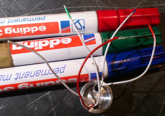
The wires were colour coded, and fitted through the new holes in the led board:
Now the soldering started, I tested the light after each colour that was connected  , it came to live! One strange thing though: the green was always on, and I discovered that on the driver a 'green' component was touching the pill (battery minus: oops, direct drive on the 14500??). Fixed that with a tiny piece of insulation tape. Now it worked fine!
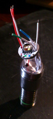
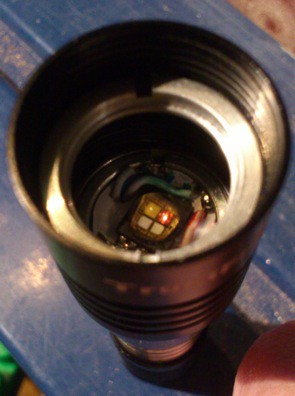
End of soldering. (sounds pretty relaxed, was actually quite an effort with all those solder joints). I sanded the outer edges of the solder blobs away a bit so that they would not touch the pill when assembled (picture was taken before that). Arctic silver under the board, twisted the massive bundle of wires into a rope (that pulled the led board nicely onto the pill as well, again: no fixing needed), the wire-bundle just fitted in the hollow area above the driver. Pill assembled and screwed inside the body:
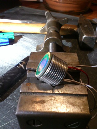
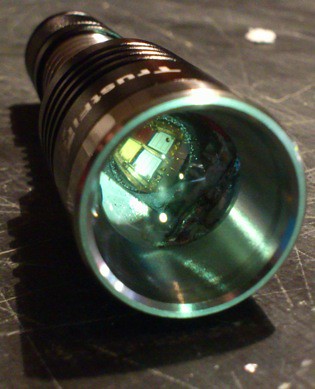
The finished light:
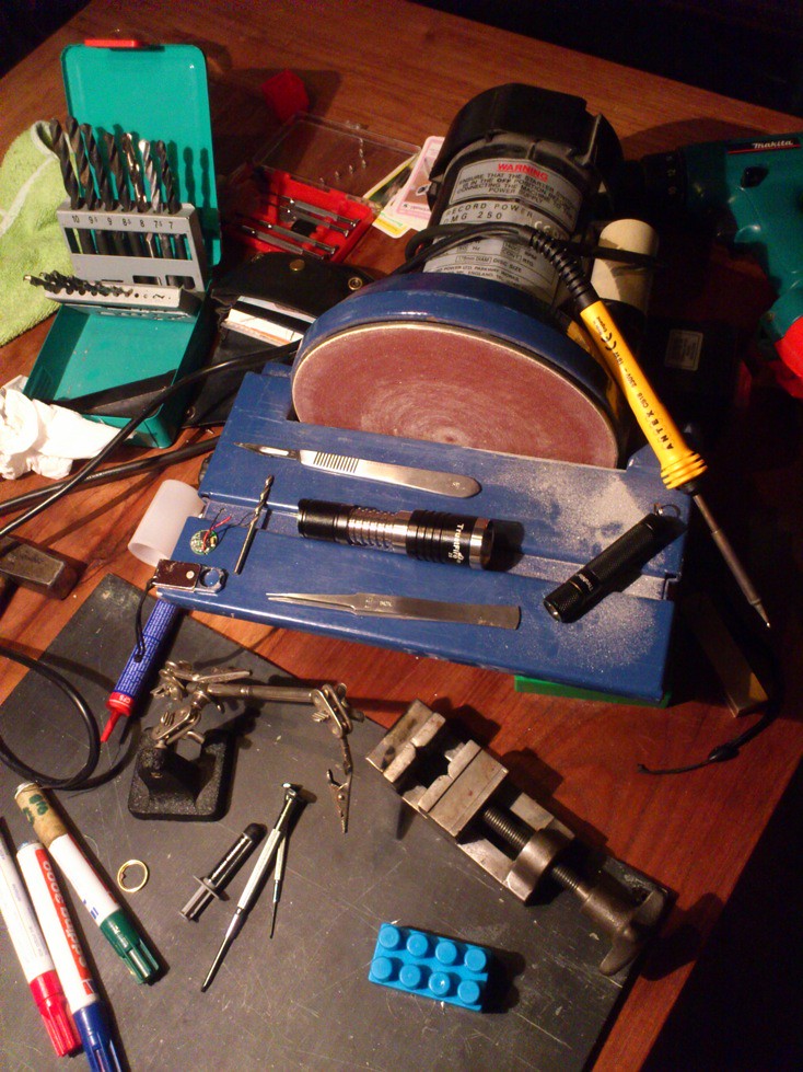
The dining table (oh, oh, within five hours my two-year old will have his breakfast here  ):
):
It was wonderfull: The Z8 was actually never designed for the xml-led as far as I am concerned, with xml the beam is ugly, the throw when zoomed in s***s, when zoomed in a lot of light never leaves the flashlight. With the mc-e (and probably also with xre, or even xpg2) throw versus flood is much better, a better percentage of the light leaves the front. Another advantage: the mc-e sits closer to the lens (it is a thick led, and the board is thick as well), so when zoomed in it just stops before that distastefull led-image becomes visable . The neutral white light of this led is the best quality light I have seen apart from the Nichia 219: a 4000K neutral that looks awesome!
Some numbers, with Nitecore 14500 at 4.1V:
tailcap draw: white:830mA, red:690mA, blue:700mA, green:0mA  (see further on)
estimated OTF lumens of the neutral white led ('educated guess' from ceiling bounce measurement with lux-meter): zoomed out:95 lumen, zoomed in:50 lumen (all that 50 lumens is in the hotspot!). That is reasonable for a AA-size flashlight.
throw at 1 meter (light switched on for 1 minute): zoomed out: 420lux, zoomed in: 4400lux (that is quite near the throw of the stock light, but that one draws 1A more current!)
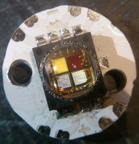
But it did go wrong eventually: I was playing around with this light all evening (the play-factor of this light is immense ), and then the green went dark. Playing some more and then the red switched off when fully zoomed out, switched on again when zooming in. Had a look at the led and saw these silicone cracks with slicone debris all around the led, the picture does not even show all the silicone debris scattered around the led that I already removed:

So what went wrong? I believe the green already suffered a lot from the temporarily short on the driver during the first testing. but the red when zoomed out? And all that debris? I first thought that the led had become way too hot (the heatsinking in the Z8 is quite terrible, the pill is alright, but then comes the ss body  ) perhaps the mc-e was particularly sensible for heat? Then I discovered the stupid truth: when zoomed out the led sticks so far out that it touches the lens. So during all the playing around, the led was squeezed flat over and over again (will I ever do a clean mod???). The solution was simple: when zoomed out an aluminium ring inside the moving head screwes against the pill. I just put in a spare key-ring of the right size in between (not even attached to anything), you never notice it is there, and it is the way to solve that. It did not repair the led though .
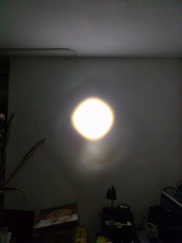
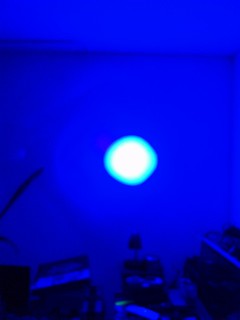
Some white wall shots zoomed in and zoomed out, flashlight is 2 meters from the wall, quite good phone camera with no manual settings, but it almost looks like how it was in real exept that the hotspot is smaller (overexposed) :


Well, as you can see:no green shots, now it is the Z8-RB, but not the Z8-RGB . (I just can not stand how i messed it up again , salary is coming in tomorrow, so I just now ordered a new MCE-color from Intl-outdoor *sigh*, the light is so nice that I am going to repair it!)
Thanks for reading, i can recommend this mod to everyone. I hope soon the new xml-color led will be for sale mounted on a pcb, for more modding fun .