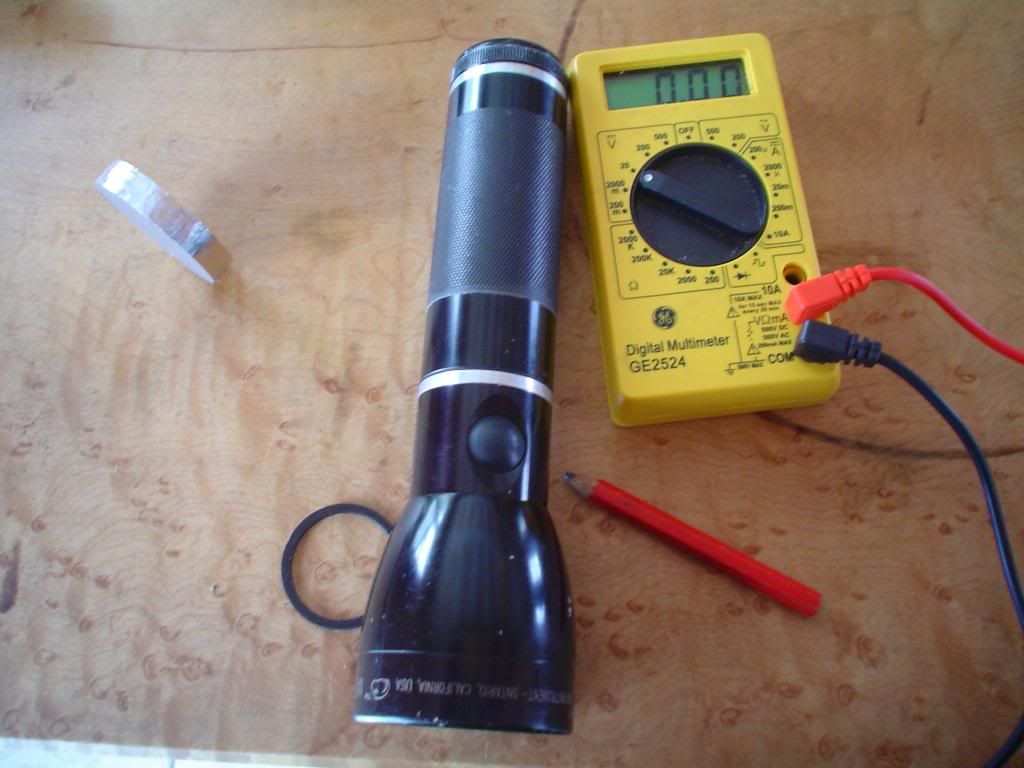
So last fall I was walking past a trash bin at a work site and noticed the butt end of a maglite sticking out. A mag charger to be precise, whose end had been used as a hammer and whose internals had been scrambled by leaking alkaline batteries. Apparently they leak when charging is attempted. The lads at the site were happy to part with that bit of junk and may have been a bit skeptical regarding my claims of future awesomeness. Then I took it apart.
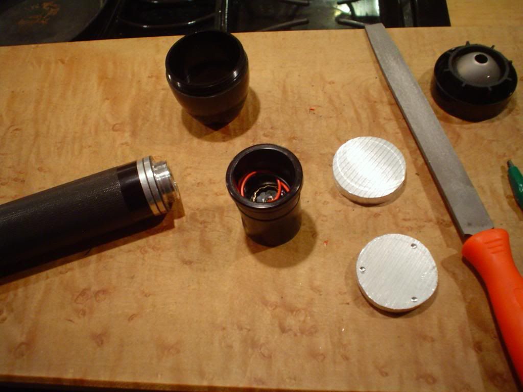
The neck is a big hunk of aluminum, great! The inside walls are tapered and the head slides on from the butt, heck and again heck! Heat sinking this light would be a headache (think tapered heatsink with a tower) and acquiring proper focus with the single position head would be a miracle. Threads on the light forums regarding modification of magchargers are understandably rare. Into the parts bin it went. But wait a goshdarn minute; the head doesn’t have that pesky internal ledge found in regular mag lites! A big slug of aluminum would fit, and so would a 50mm tri-optic. But who needs a 3D mag of any kind in these modern times of the human lathe? On to the marking and the tapeing.
Cutting is done, here are all the parts. Note the cutting done on the inside of the neck to accommodate the narrower stepped portion on the bottom of the heatsink.
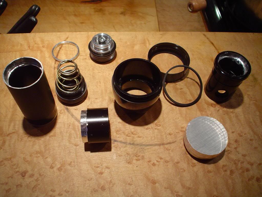
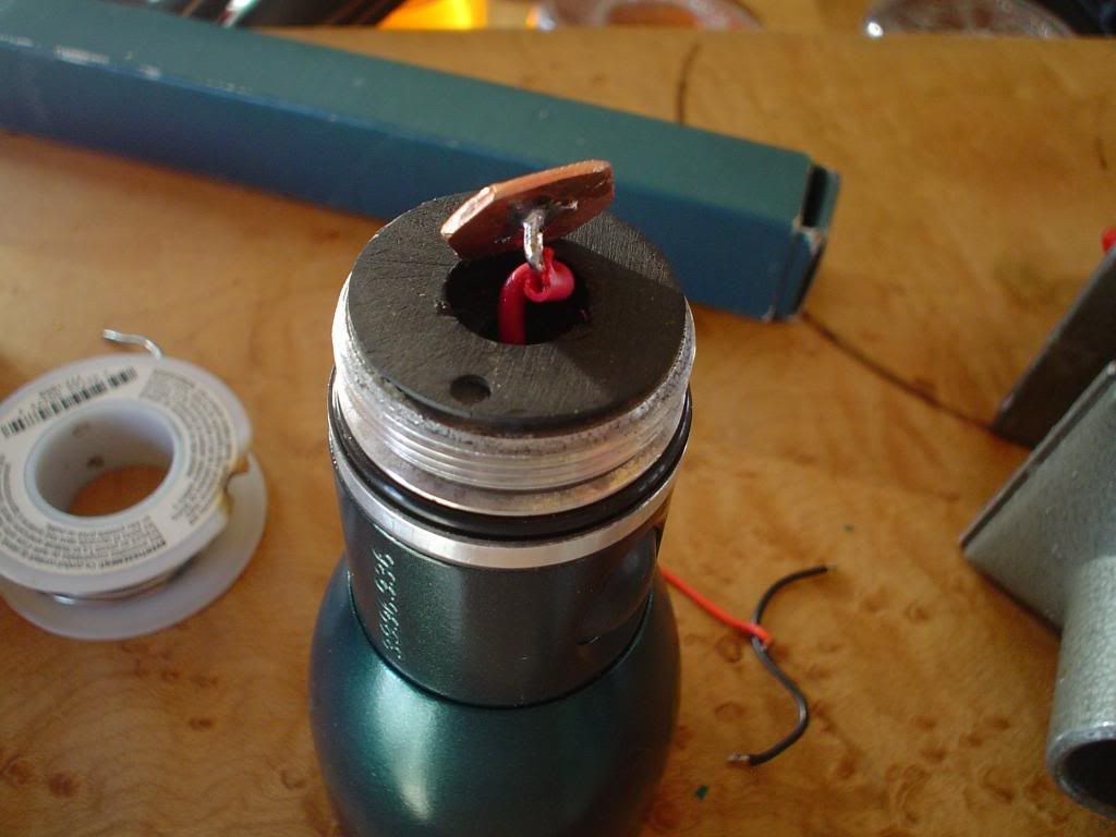
The tube is ready for the epoxy. The screw in the top of the charging receiver was my first attempt to make the host work with flat topped batteries and carriers. The two part screw together host is an electrical resistance factory. I'll deal with that later.
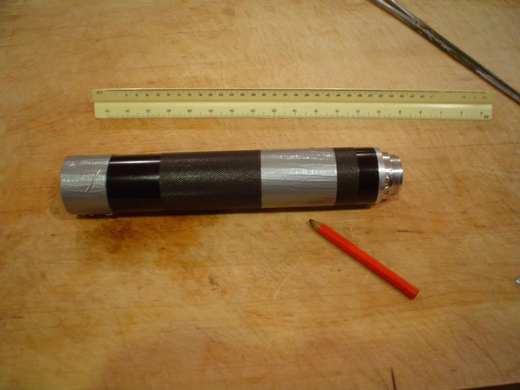
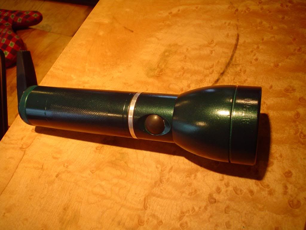
A shorty is born! I made it roughly a 1 ¼ D cell length to accommodate **650 cells while using the stock tail spring. Yes, the tube can be attached in reverse.
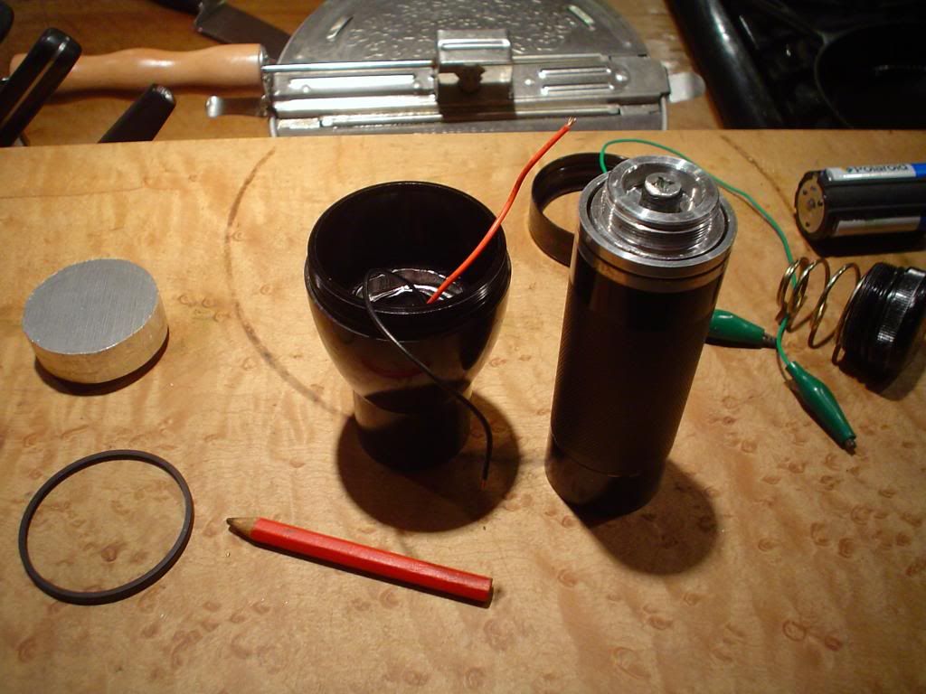
The heatsink is ready. The three XM-L U2 1B are secured with Arctic Alumina. The switch body needed shortening and wires needed to be soldered in place to accommodate the transition to LED technology much the same as a standard maglite.
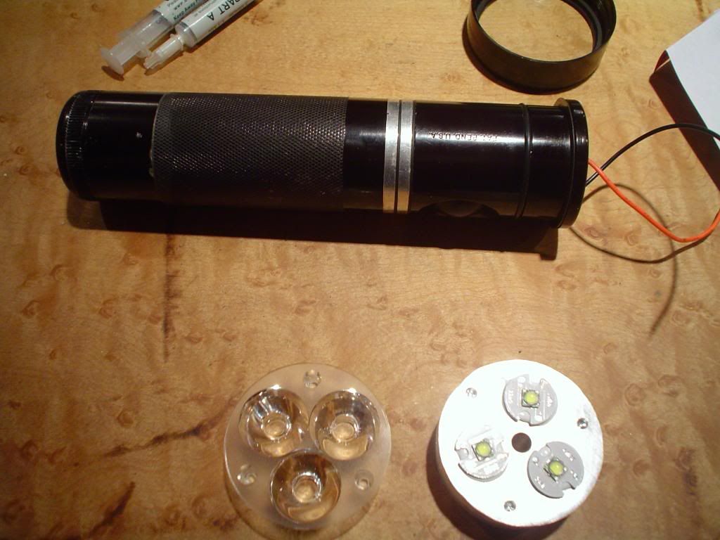
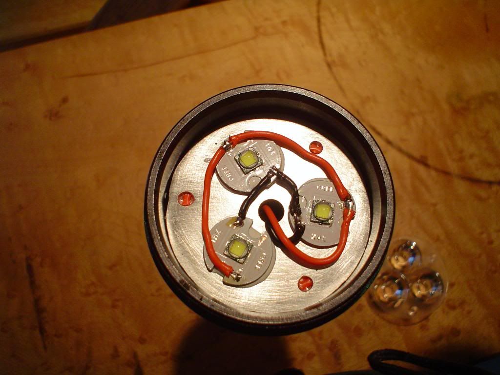
The light engine is wired in parallel for direct drive. Those little chunks of red wire in the tri-optic guide holes are there to hold the optic away from the emitters to form a more perfect focus.
Initial tests confirmed my suspicion of high resistance. The light drew 7.5 amps off an INR 26650 which drove a similar light to over 11 amps. My fix was to directly connect the positive battery contact inside the tube with the rear contact of the switch with a 16 gauge stranded copper wire. The tailspring was also modified to reduce resistance using the old wire through the center trick. Switch internals were cleaned and lightly sanded. The light can now draw over 9.5 amps.
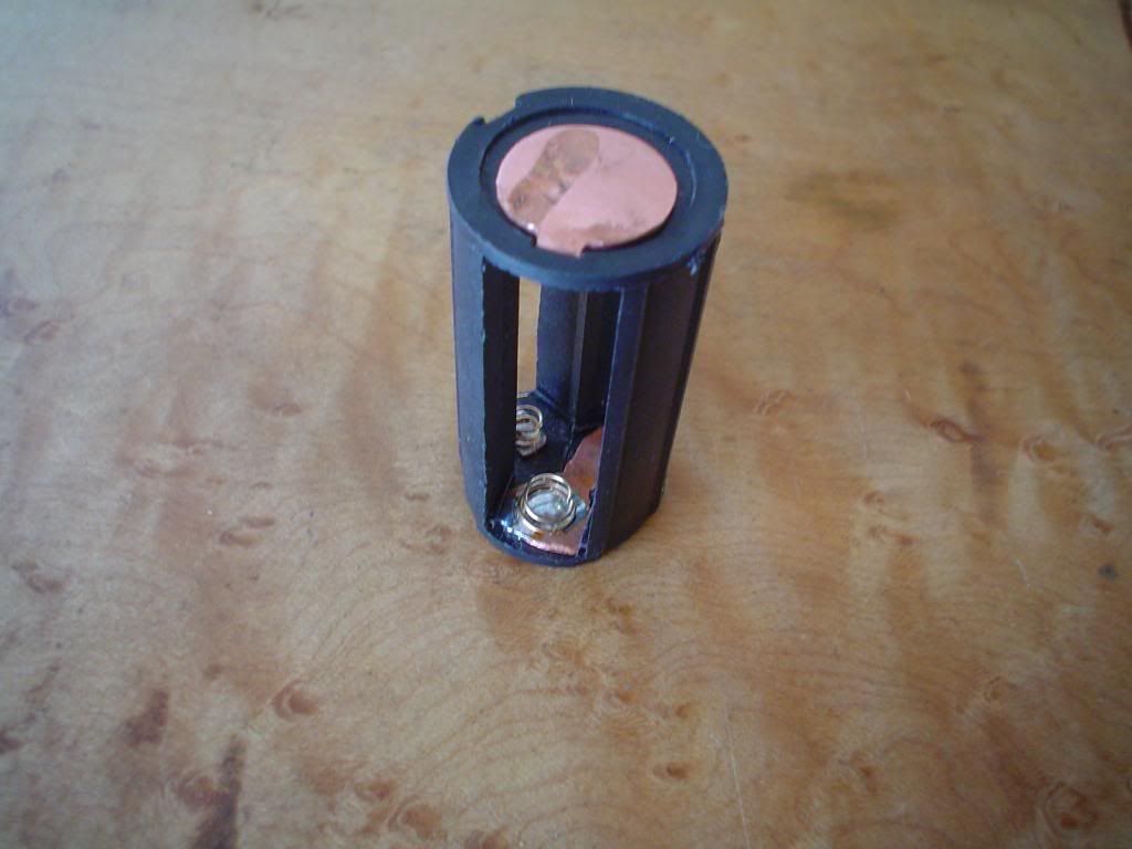
My original intention was to make this light multi fuel capable. It can be run off any appropriate 18650 or 26650. To expand the available fuel options I modified a triple AA battery carrier with copper contacts and thick springs. This carrier will draw over 5 amps out of 3 eneloops for a short while and settles nicely at around 4 amps. Every time I make one of these carriers I need to cut a piece of copper pipe and beat it flat. I really need to buy some copper sheet!
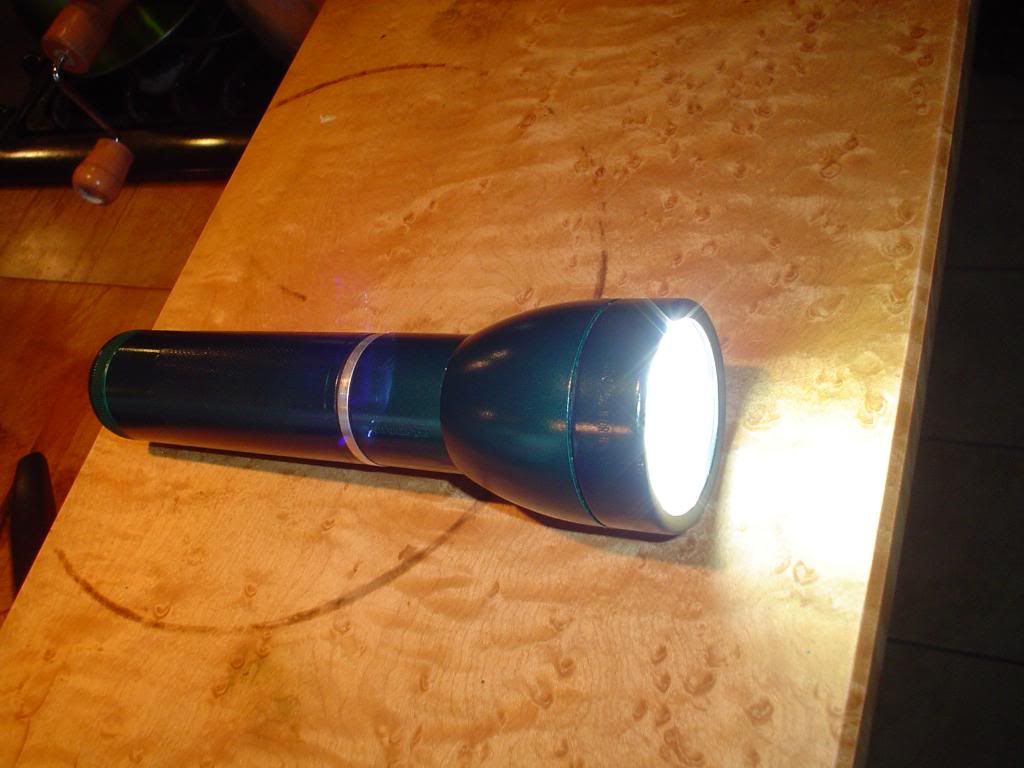
It’s bright!
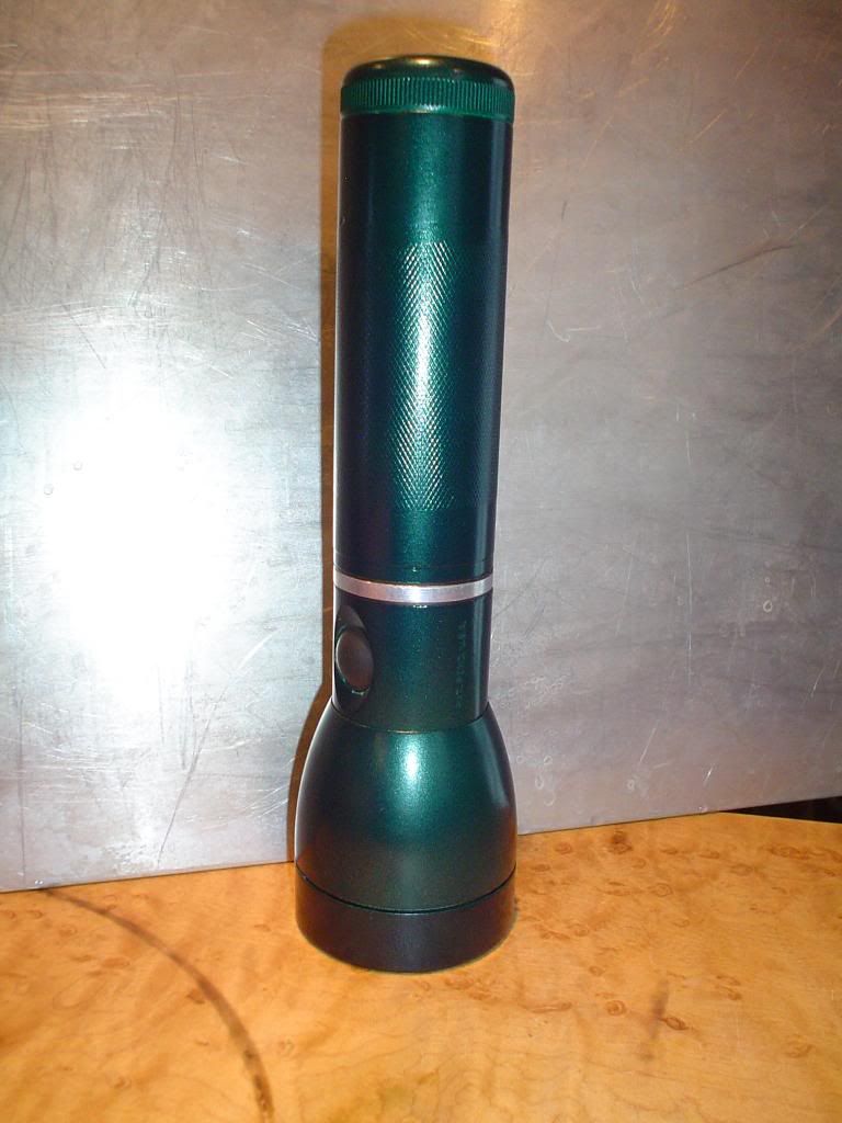
Oh yeah, I painted it green using a nicely shaded automotive paint! Mistake? Only time can tell but it sure looks good to me.
This was a fun build; there were more complications and obstacles encountered than when modding a standard mag but there is a certain degree of satisfaction in creating a couple thousand lumens from a garbage can.
Thanks for looking,
KY

