i have modded a Nanjg 105c with a zener mod like we do for the MT-G2 and i have tried it with 1 cell to drive a XM-L2 but it is giving very low current and when i tried it with two cells and 2 xm-l2 in series it worked great
problem is i want this driver to be able to take high voltage but to run only one XM-L2
It might work if you heat sink the 7135’s really well. You will loose a lot of efficiency because the 7135’s will have to “burn off” the excess voltage. I think the 7135’s may fry fairly fast though.
Yes you can, but not for long time. AMC7135s are rated up to 7V difference Between input voltage and output. At 8.4V with XM-L2s Vf of 3.4v at 3 amps AMCs must dissipate more then 4V if you include voltage drop under load. Without serious heatsinking driver will not be happy. But why would you drive xm-l2 with zener modded driver anyways… Nanjg 105C is only 3$ or so.
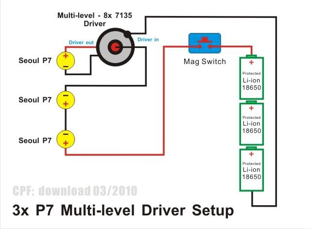
I have modded 3C mag to triple XM-L2 setup with this method
1st i have tried normal Nanjg 105C but at low i found the Driver is taking about 6.5 volts after about some days of use the driver fried and giving only very low current well i tried another driver same thing happened
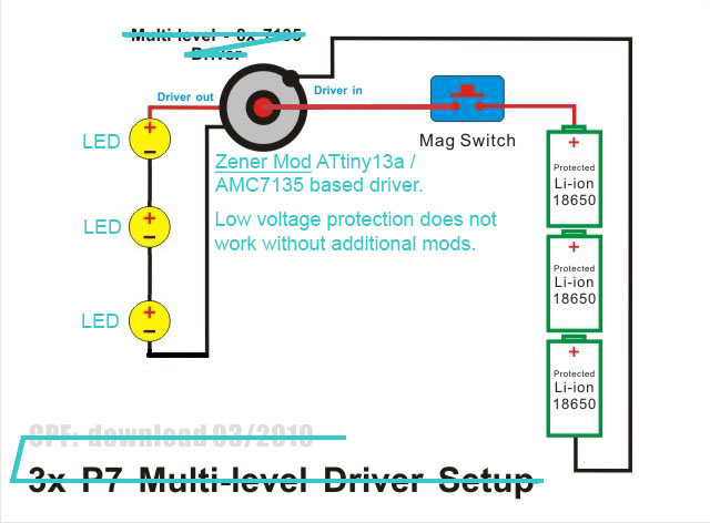
so i decided to try zener mod to protect the driver from the high voltage when using it at the low mod
well i did the mod and gave it a try it worked but the leds is running at very low current so i tried to test the driver with the following
1:- 1 LED and 1 cell = very low current
2:- 2 XM-L2 leds in series and 2 cells in series = the normal output of the driver 2.8
When driving 3s1p emitters 3s1p Li-Ions and the configuration in the picture you posted the “zener mod” is not appropriate.
The driver does not need to be modified when wired the way the picture shows. That wiring style is much older than the zener mod and it does work fine.
Stop trying to use the zener mod in an inappropriate way and you will not have a problem.
A stock 105c will drive a single XM-L2 at full brightness using a single (4.2v) 18650.
the problem with A stock 105c it is geting fried when used at low mod because the driver is getting almost 7 volts and i am not using it at low on purpose but you have to cycle to get the next mod you want, you know what if i just can remove the low mod there will not be any problem
Nevermind, that checks out. IIRC that wiring was for drivers without an MCU.
Do the Zener mod, but fix your wiring. All three emitters should be in series between LED- and +. If you use the “download” style wiring from your pic I’m not sure what the effect will be. The voltage might not be high enough for correct Zener operation when using the stock Zener mod resistor.
It’s a bit confusing whether it’s one or three LEDs and/or 3 cells in series. Wouldn’t you use a higher value resistor for the Zener mod with 3 cells instead of 2?
OL, his thread is really confusing. It all comes back to troubleshooting he was trying to do for a triple setup. As far as I can tell he doesn’t actually have a need to run 1 emitter on 2s. He Zener-modded the driver and then tried to test it with 1 emitter and 1s.
RBD - at some point there will be a problem w/ too much power across the Zener unless resistor value is increased. I just assumed we are still ok, did not do the math though.
Leaving the same resistor value definitely increases current when voltage is increased.
It’s the excess voltage that’s the issue which is why userdownloads method worked. What’s often missed is the part where it describes how much trace area is needed to dissipate the excess wattage. It mentions up to 1000 square millimeters*per chip* and you’re not going to find that on any nanjg board.