Update - 14/07/15
SUCCESS!!!
It turns out the components in the tailcap switch weren’t coping with the current of the high drain batteries and the resistance was causing massive voltage sag and the driver was going into low voltage protection. So I pulled the switch out tonight and made a few tweaks to it including removing one of the little FETs, removing the switch, rotating it 90 degress and gluing it back down with some epoxy then I bypassed all the components with some 18awg wire.
Well it is working perfectly with all types of batteries now and this thing is a monster with plenty of heatsinking!
Now to make another one with some XP-L HI emitters!! J)


On another note, I’m pretty happy with the camera on my new Samsung Galaxy S6. My old S4 never took night time shots like that even with the bright lights.
UPDATE - 11/07/2015
Emitters arrived, 10507 optics arrived, driver arrived, new UCLp lens arrived, ordered a blue oring which is 1.8mm instead of the stock 2.5mm. Battery carrier has been beefed up by running a length of copper braid over all the traces and braiding the springs.
This morning I machined the copper heatsink and the pictures speak for themselves!!


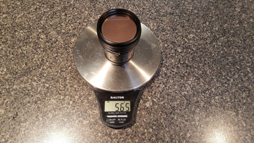
Yes that is 417g (14.7Oz) of copper!!! and it is a slip fit into the head and fully contacts the original emitter shelf.
Update - 18/06/15
Well the project is officially going ahead!! I have spoken to a few people, emitters are ordered and I decided to go with 12x Nichia 219BT emitters mainly because I didn’t want the XP-G2s as I would only get the 3D emitters and then it would pretty much have the same beam as my M43, optics are ordered, I have organised a driver solution with Richard and today I picked up a big chunk of copper which will be made into the heatsink! There will be a little bit of a waiting game whilst everything is arriving, then I will need to machine the heatsink to suit. Whilst I am waiting for all that to happen I will be beefing up the battery carrier and I have already stripped the original driver which is becoming a contact board.

Hi All,
I have had my Thrunite TN30 for quite a while now and I resistor modded it a while ago and de-domed the emitters and it was fine for a while then one day it stopped working. Since I started modding lights this one stopped “wowing” me and it got me thinking that maybe I could do something with it. So getting the itch to do a decent sized mod again I have decided to do strip it out and go for it.
I haven’t got a full plan in place yet as I am not 100% on the circuitry side of things. However, I am going to get a 2” diameter copper bar and machine it into a big heatsink. I was planning to strip the original driver to use as a contact board and then use a FET driver if they can be used with a 3s battery configuration?This is where I get a little stuck as I am not sure what is required to wire up multiple emitters. I know the battery carrier is wired in series and as such puts out 12v but how does that translate into me running multiple triple boards? Is it possible? The heatsink will be 50mm in diameter which means I could fit up to 4x 20mm triple boards on it.
As soon as I can figure out how it will need to be wired up I can get stuck into collecting parts for it, so I am hoping to get some help from those of you who know this side of it better than I do.
I had also considered using multiple MT-G2s or XHP70s but I don’t want a mule set up.
