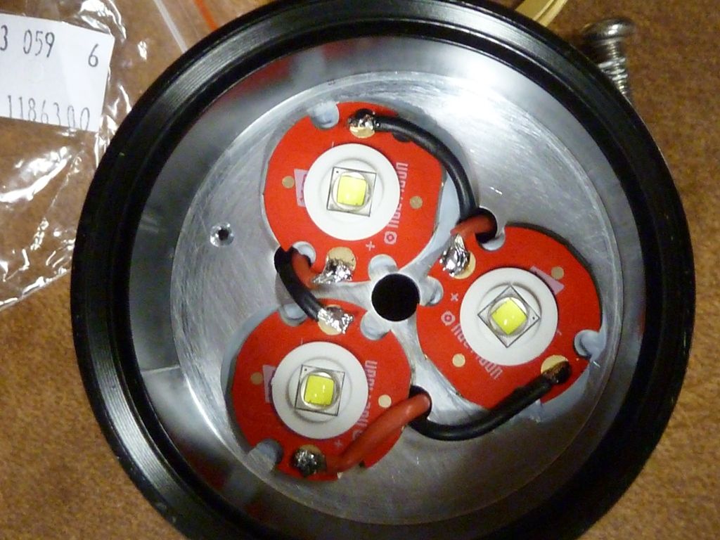
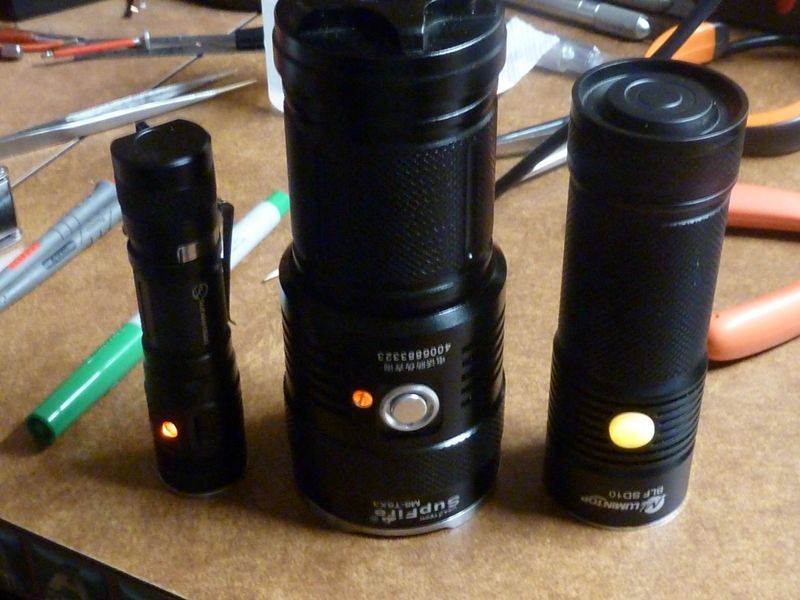
Hi everyone. So, long story short, I got tired of waiting for a Supfire M6 Mod2 to come in stock, so I ordered the parts and did it myself. I got all the way through but made some mistakes, one of which was shorting the MOSFETs and making some wonderful magic blue smoke. When I finally got it all together, I noticed that two of the LEDs were not as bright. On turbo mode, the Supfire M6 was only about 1.5x as bright as my Zebralight SC62w which definitely couldn’t be right. Taking photos of the light, two of the LEDs are obviously dimmer (the two that I’m pretty sure I shorted the MOSFETs on). So I ordered some new MOSFETs to replace them hoping I can get the full brightness. That was all last week.
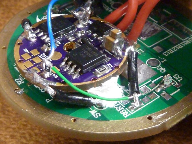
The MOSFETs came in and I replaced one of the degraded ones so far. On turbo mode, two LEDs are now super bright now, so it was definitely the MOSFET. Now, the problem is that this new MOSFET has a higher Vgs threshold voltage; FDD6676 1V/1.5V/3V Min/Typ/Max compared to the original DTU30N02’s 0.6V/1.5V Min/Max. When scoping the gate, I see that the voltage hovers around in the original’s MOSFETs threshold, allowing it to turn on. The driver driving the MOSFET is a 7136 chip, with the sense resistor ‘shorted’ out using the copper braid from the Mod kit. The 7136’s documentation is pretty crappy and I’m wondering if anyone else has any better details on what it should be doing. Should it only be outputting ~0.8v when a PWM signal is applied to the VDD pin?
So as for finishing the mod, there’s two ways I can go:
Find a MOSFET that better matches the original (I couldn’t find . I only bought the FDD6676 because it was cheap and readily available on ebay. But I may just do a digikey order for a set with closer specs.
Bypass the 7136 and use a RC circuit on the new MOSFETs by adding a resistor between the PWM signal and Vg, and Vg and GND, and using the MOSFET’s gate as a the capacitor. I’ve tested it with the replaced MOSFET and it seems to work fine. Does anyone else have any experience, thoughts, advice on using an RC circuit? Anything I should worry about, such as temperature drift? I’m planning on using two trimpots. (One of the reasons why I’m looking at using a RC circuit is because driving the gate directly with the PWM is still too bright. I may look into reprogramming the board later, but I’m going to leave it as is for now.)
I was originally thinking of doing #2, but now I’m leaning towards #1 because it seems there’s less that can go wrong. I’d just have to wait for the new MOSFETs.
Edit: I just ordered some AOD424’s. They should be an almost exact match.
I am unsure of option #2 as I do not have the circuit experience. #1 sounds like it will work and get the driver back to “normal”, so that should work.
What would the advantage be for #2?
It stinks when a mod goes awry, but it is great when it gets fixed and works, hope this does I for you…
Option 2 would eliminate the need for the 7136 driver. The advantage would be that the light level would be fairly adjustable, and it wouldn’t rely on the 7136, which seems hard to get a hold of, and has little documentation based on what I can find online. The downside would be that I’d lose any features the 7136 has to offer, such as low voltage cutoff (if the Mod2 driver doesn’t automatically do that).
Anyways, I’ll try better matched MOSFETs first, and if that doesn’t work, I will look into other ways.
When I’m saying Mod 2, I’m talking about the Mountain Electronics Supfire M6 mod. The more I look through this forum, the more I want to pick up another and do my own modding after I’m done with this first.
I have to say, I was pretty surprised at how easy and how much space the M6 gives you for doing mods like this.
Love the driver retaining ring on this, and the nice LED shelf, plus the solid body, SS bezel, switch is a good one, etc. I can easily upgrade the firmware because the driver comes out with no de-soldering. Yes, lots of room.
Really, really wish you could get a 5 LED version of this, or more. Was thinking of seeing if a 5 LED reflector from another cheap SRK clone would fit in the M6 - that would be awesome.
Read thru Richard's mod #2 description many times, but not sure what it is exactly. It's probably in a thread somewhere. Think he based it on the earlier reverse engineering and experiments being done on the SRK's and the M6, where he probably was directly involved with. Way back when the SRK first came out, there was some really good re-engineering goin on here on BLF. At the time, I couldn't even follow or understand it all. This is where it all began, a classic BLF thread: https://budgetlightforum.com/t/-/11403.
Well, I just got the new MOSFETs in and it doesn’t behave like the original. The waveforms looked different despite the data sheets saying they should be fairly similar. Maybe it just needs to be matched pretty precisely.
I decided to just go with #2 and do the RC circuit. I put in the higher Vgs MOSFETs and removed the 7136’s. I then added a trimpot from the PWM signal to the gate, and adjusted the resistance. This should effectively create a RC circuit between the MOSFET’s gate as a capacitor and the resistor. So far it seems to be working fine. I’ll have to play with it some more to see if I run into any issues.
Brightness wise, it seems to be about 2x brighter than my Zebralight SC62w. If the SC62w is putting out ~1000 lumens on its highest setting, then is it safe to assume that the M6 is putting out closer to 4000? You need about 4x the lumens to double the perceived brightness, right? I’ll have to see if I can do relative brightness measurements with my camera.