So I have wanted to something like this for a while, which is to create a data logger. More specifically to log solar current and battery voltage during during a battery charging cycle.
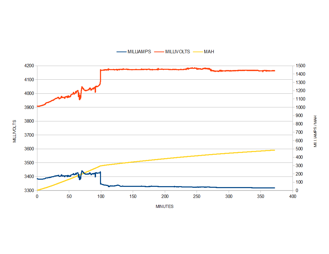
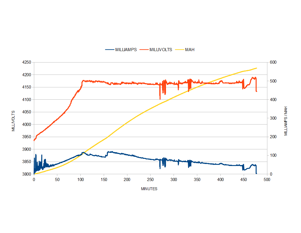
To start things off, I will chart a TP4056 module charging a li-ion battery. In this instance USB power will be used, and logging will be done thru the PIC16f1783, usb/ttl serial module, and Bray’s Terminal. Then it will be followed up by using the solar panel as the source to the TP4056.
DATA LOGGER
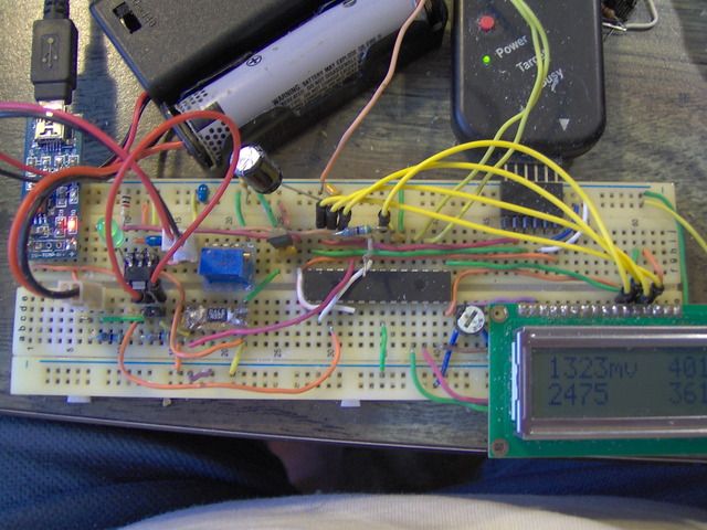
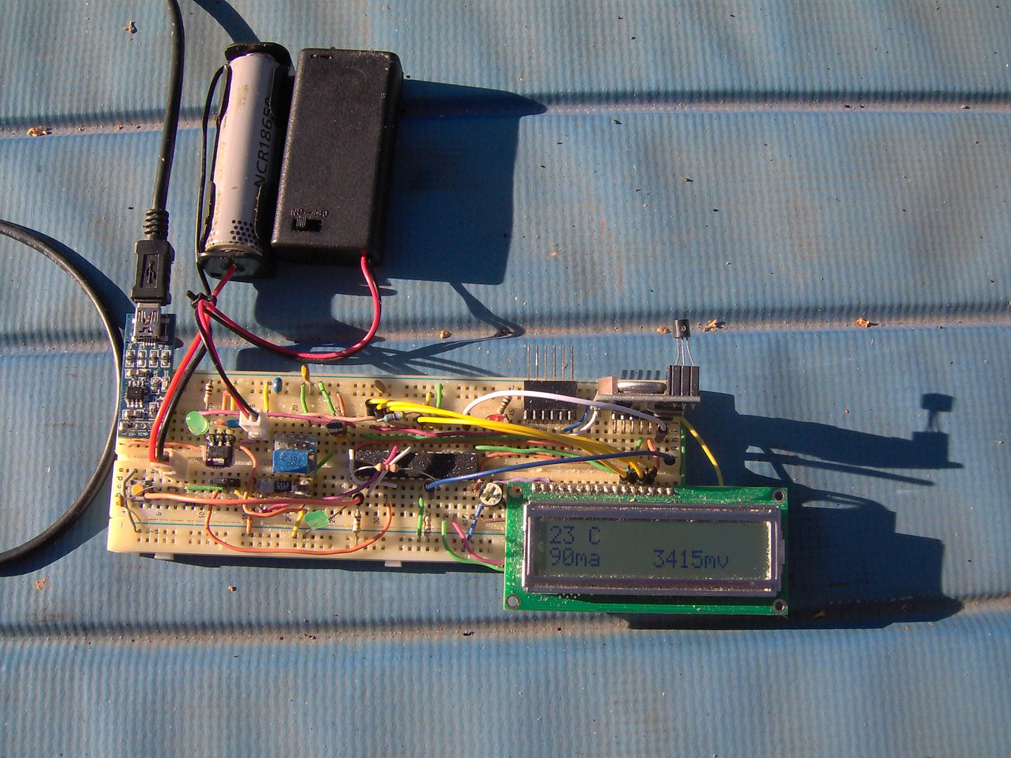
Going with a PIC16f1783 which has a 12bit adc module, and a couple of op amps too. A R33 ohm current sense resistor is used on the low side of the battery to measure the current. The voltage signal is processed thru an op amp with a 10x gain and sent on to an adc pin. A 25 turn precision pot is used to tune the OPA for the 10x gain based off the sense resistor value read by a DVM.
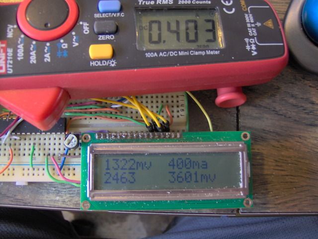
I found that generally speaking that the logger is within a few ma of that read by the UNI-T 210E readings (i.e. if I press the zero button enough, and get the orientation right). The millivolt readings are a couple of mv’s low from the DVM readings.
The TP4056 puts a lot of noise in the circuit, which makes measuring the current challenging. Using the 12bit adc, and taking a large number of samples really smooth things out. In this case, 1023 samples were used for both the millivolt and milliamp readings. An I2C combo eeprom and rtc module will be used to help out storing the values.
TP4056
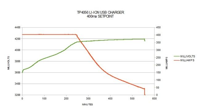
The TP4056 module current resistor has been changed to 3K ohm to bring it more in line with what the mini solar panel(s) puts out. This gives a 400ma charge current during the CC phase, and will terminate at 1/10 set current or 40ma during the taper phase.
MINI SOLAR PANEL
Here is the 1.5W mini solar panel that will be used. I measured an Voc of 6V, so it will play nice with the 8V max of the TP4056.
USB POWER TP4056
SOLAR POWER TP4056 LOGGING+
The handy little I2C module has everything a logger would want, an 32Keeprom, DS1307 clone, and even pads for a Dallas one wire device, so put a DS18b20 temp sensor there. One note on the DS1307, and that it is a Chinese clone. I found that out when playing with the square wave out bits, and they do not match the data sheet ![]() .
.
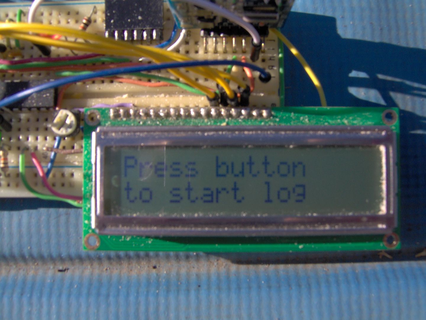
A lot of time spent on the logger interface, and operation. First to log the millivolt and milliamp data, which wasn’t too hard. Most of the time was spent on the user interface and formatting the data to produce a csv log file by reading back the eeprom values to Brays Terminal. So:
1) Plug in the solar panel
2) Turn on the power to the PIC
3) Announce to user waiting for a button press (.5 sec)
4) Wait for RTC to start log on Seconds = 0, record start time
5) Start logging and each 10 seconds after, using RTC 1Hz square wave output
5) User button press (.5 sec) stops logging and record stop time
6) Announce to user waiting for uart character from terminal
7) Send uart character from terminal
8) Start micro to reading eeprom values and sending back thru uart to terminal log file
9) Announce to user uart transfer complete
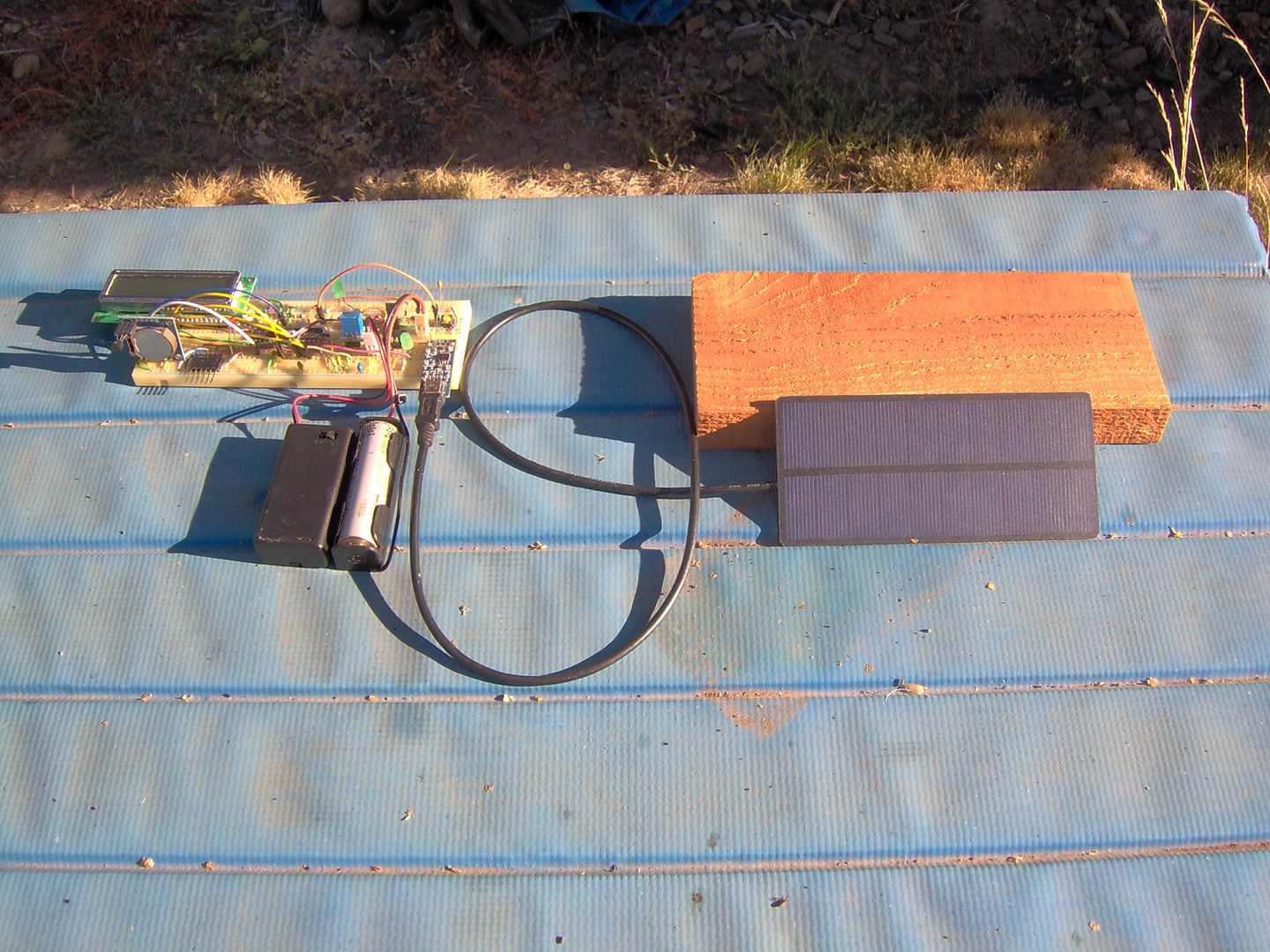
Cut and soldered a mini USB cable to the mini solar panel. This makes for an easy hookup to the TP4056 module input, and with a mini to micro convertor, it could plug into a power pack, or other chargers. Might have to try that with the LiitoKala Lii-100.
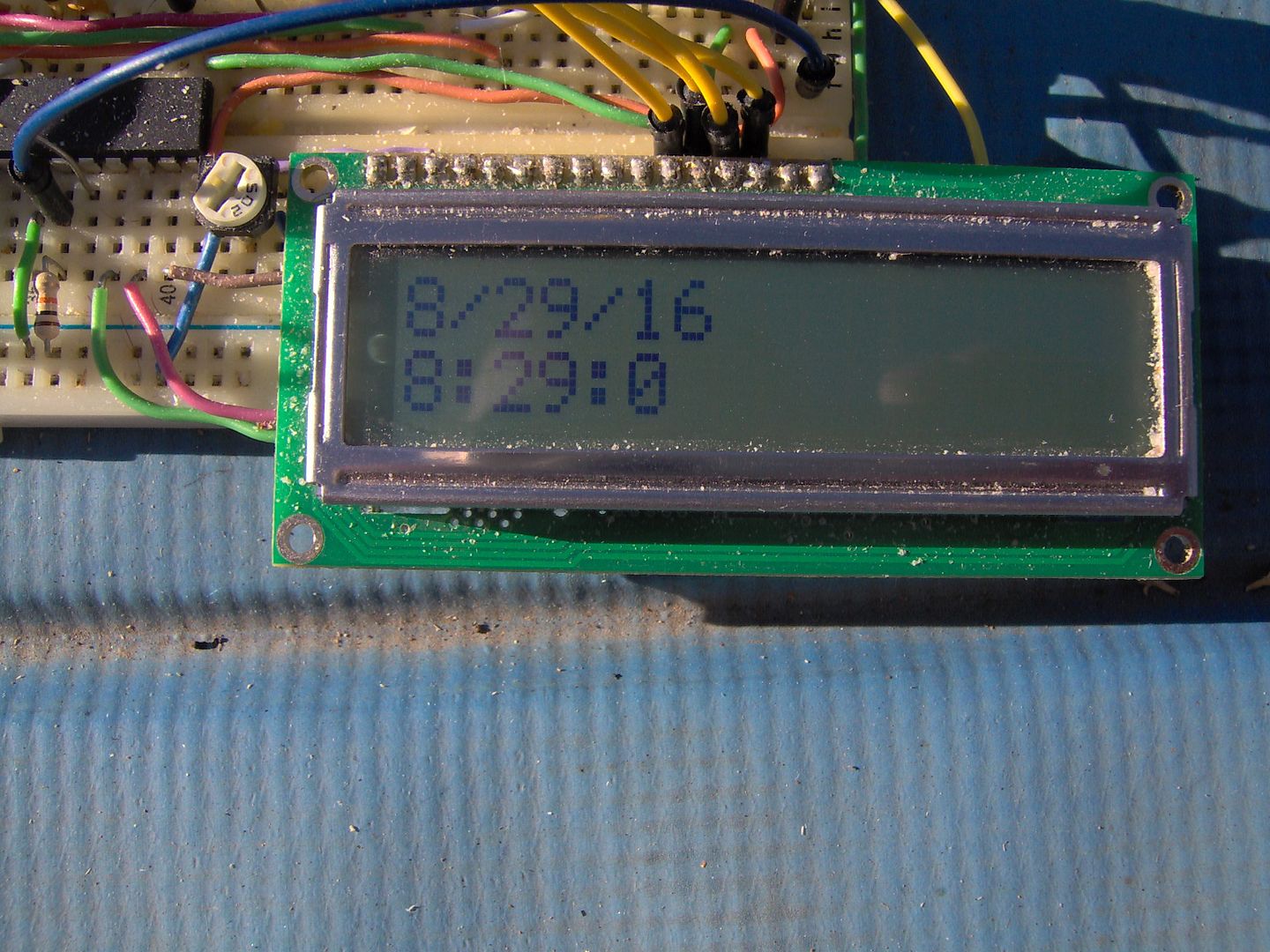
Set everything up on the camp table, and started logging at 8:29am on 8/29, now that’s a good sign. If Karma is working then I will get back a full set of un-corrupted data back at the end of the day. Nice clear sunny skies forecast for today, so should get strong uninterrupted? charging conditions.
Initially I was looking forward to a partly cloudy day to see how the interruptions to charging would affect the TP4056. But I don’t think it will be problem as a reset from the input side re-initializes the charger and should take right off again, at least that was my experience with the USB input. Now removing the battery while charging is a different matter.
Well the first logging session was kind of a bust. I had started out using a 32kB eeprom, ended up with a 32kbit (not byte) with Chinese I2C module. Oops! overran the data set and so it was corrupted. Had to bring out an old DIY I2C module built long ago with a DS1307 rtc, 24LC256 eeprom, and DS1721 temp chip. Little more work, and back to to it.
Put the cell on the Opus for a discharge and got 1570 mah, pretty good for a days work on a really sunny day.
Let us start logging until we see the green light from the TP4056?
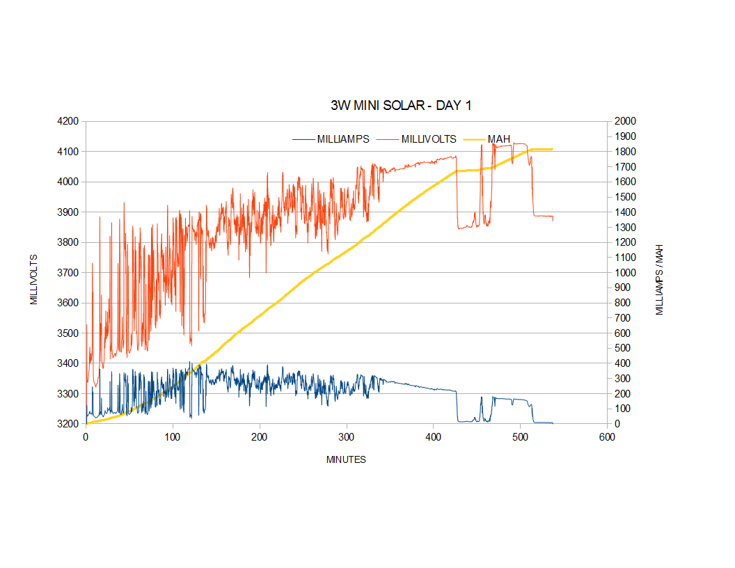
DAY 1 SOLAR LOGGING
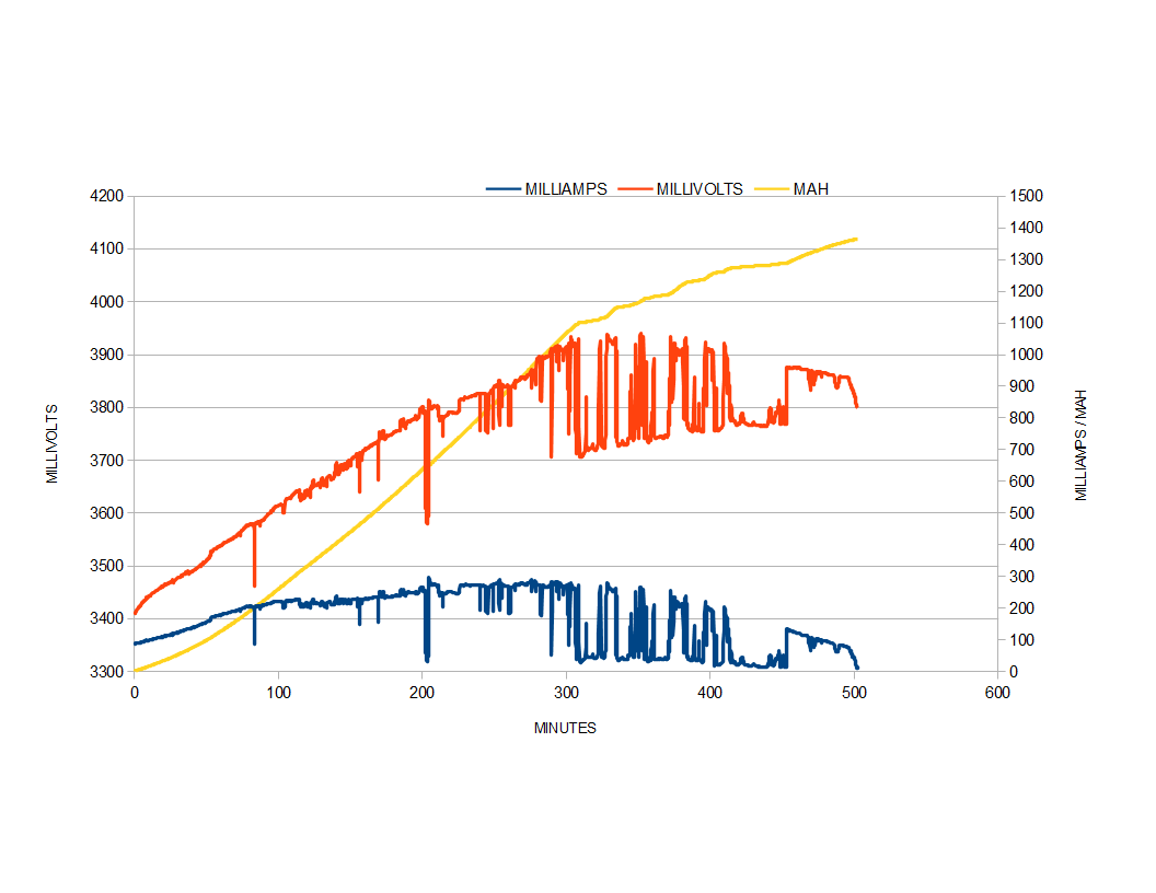
As seen from the charts a partly cloudy afternoon on Day 1 sent the charging current bouncing up and down like a yoyo. Max charge current observed was about 290ma. The calculated charge capacity was 1372mah, not too bad. Battery voltage started out at 3414mv and ended at a resting 3792mv.
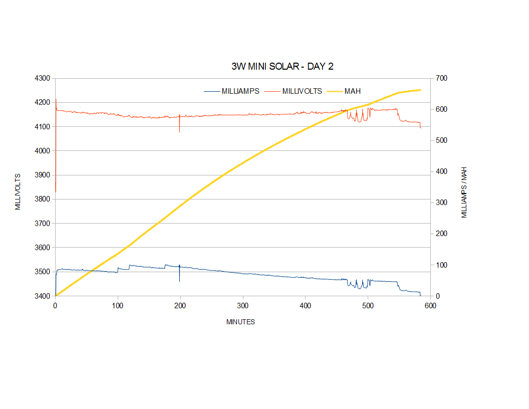
DAY 2 SOLAR LOGGING
Day 2 was a different story altogether, with thick clouds moving in, and not letting any sun to speak of through. Pulled the test early, because it looked like it was going to rain any minute. The mini solar panel was really struggling to maintain a charge current here. A max charge current of 212 ma so obtained, so it never really had a chance to kick into high gear. Much of the day was spent in the 60 to 30ma range. The calculated charge capacity added was a mere 484mah. The resting voltage started at the 3792mv and ended at 3934mv.
The graph looks like it has encountered the CV phase, but not much is happening :person_facepalming: .
DAY 3 SOLAR LOGGING
Well we finally made it to the TP4056 charging complete green light! Definetely into the CV part of charge curve, but unlike yesterday, the clear to partly cloudy day had enough overhead current to finish the job. Just like any Li-ion charger, it takes a long while to pack in the last bit of charge into the battery cell. So adding up the calculated mah for each day, we have 1372 + 484 + 568 = 2424 mah total. This would be less than expected range for this cell of around 2800 mah. But it is quite possible the start voltage was a little high. Only a discharge on the Opus will settle the score. The final resting voltage for Panasonic NCR18650 2900 mah laptop pull was 4.132V.
SUMMARY/CONCLUSION
The 1.5W mini solar panel is good enough for a good partial charge (1300-1500 mah) with sunny conditions if used on a daily basis. Over a few days it would be reasonable to assume a near full, or full, charge on a sub 3000 mah li-ion battery in sunny to partly cloudy conditions during the summer.
Well, more power needed, right? I’ll twin up a couple of panels for a 3W configuration and see if we can quicken the pace up a little.
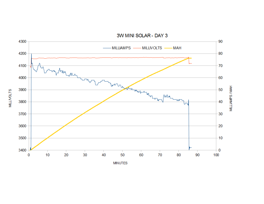
3 WATT SOLAR GRAPHS
So with two 1.5W panels twinned up, I’m thinking the Panasonic NCR18650 would be charged up in half the time right? Well not so fast, because of the long taper charge spent is spent in the territory where a single panel would suffice on a sunny day to partly cloudy day.
The first day is able to pack in an extra 450mah over the 1.5W panel. More could have been contributed if not for better than the first half of the day was partly cloudy. The USB charging, starts the CV part around 4150mV, while solar charging started around a 0.1V early at 4050mV, a lot more mah could be packed in that time/space before the taper charging. This sets up for extended CV charging as witnessed by the following charts.
The second day was sunny but a whole lot time spent in the taper charge area, way to long it seems. Should have wrapped charging and got the green light, but no! ![]()
Guh, still more CV charging to finish up.
SUMMARY/CONCLUSION
Three watts of power doesn’t mean 1/2 the charging time with the TP4056. Solar charging spends too much time in the CV phase of li-ion battery charging using the TP4056. This could be due to a variety of factors which need to be explored, the main culprit being early CV initiation at 4050mV.
Some ideas on the why and for the early CV phase charging.
- The logger itself loses around a tenth of a volt over the low side 0.33R sense resistor. Have parts now to use a lower value R and a high side current sense opamp. Also a hall effect current sensor could be used which typically only loses only a couple of mv.
2. The constant start and stopping of solar power during cloudy/shade conditions could be confusing the TP4056 on when to start the CV phase of charging?
3. Changing the TP4056 current setting resistor to a higher charge from the current (400ma) could could possibly see a shift in the CV phase due to the higher termination setpoint.
Irregardless on the problems presented for solar charging, the first day of 3W charging put a very usable 1800mah (calculated) charge into the NCR18650. And talking about the calculated 3W charge to TP4056 green light, it was 2553mah. The battery was then discharged by a Opus BT-3100 V2.1 at 1A and the result was 2772mah. So my calculated charge is low, or the Opus is high, or somewhere in between?
[Future LiitoKala Lil-100 solar test?]