Can someone in the know explain to me how the LDO drivers work in general? I am familiar with using voltage regulators in a power supply type circuit, but not so much how to make them work for an LED driver. I did a search and didn’t come up with much information, so it might even benefit someone else if we can get a simple description.
Are these PWM’d? Is the regulator circuit set up with a particular constant current and 7135’s used to add more or less to that?
Can/Is a digital potentiometer be used so the 25/45/85 can adjust the regulator circuit?
I'll take stab. Not sure how detailed the question is meant to be. Linear regulators are just controlled resistors, transistors used in a linear-ish regime, not as an all or nothing switch. The amount of resistance through the transistor is determined by feedback off the output voltage or current, by a an amplifier that sends a difference signal (difference between output and reference) back to the transistor gate. It's a negative feedback, so if output is too low, the transistor opens up more. If too high, it closes down more.
In the end though, it is a fancy resistor, not a transformer. If the question was more about the difference in an LDO and other linear regulators, I'm not as clear on that but it seems there are differences in high side vs low side regulation (does the regulator sit between load and + or load and - ) and how close to saturation (fully open) they can get. These seem like details relative to the basic operation though.
An LDO is simply a stable liner voltage regulator. Some models do offer adjustable voltage output as well.
The issue here is that they are useless for what you are thinking as they have a current limit of only a few mA so it could not be used to drive an LED (at least not as well as a 7135 for the space/current).
There are linier regulators that can work for LED driving, OP-Amps work well and is what is used by the LD-2 driver. I had considered building an OPamp based driver at one point but decided to go to the far superior buck driver instead.
Linear regulators burn off all the excess voltage as heat, this is why the LD-2 has the overheating issues and needs the fancy board design and a good heat path to the host to keep from over heating. Besides that they work great at regulating power but you are not going to get a lot of efficiency boost compared with a PWM FET driver.
A buck driver on the other hand actually converts the higher input voltage to the correct output voltage and as such you get efficiency as high as 90% better then a linear driver. The issue is getting a buck driver to handle high currents in a compact area.
Basically when you boil it down for our uses you are better off with either a PWM FET + 7135 driver or jumping right to a buck driver (or boost driver, although those are harder still then the buck drivers).
Buck driver is the best option for flashlights if you can get it to handle the output you want.
So the LDO regulator is only used to supply power to the MCU, specifically in a multi - series - cell arrangement, rather than being in the driver circuit - that’s the part I was missing. Thank you.
So if we ignore the issue of heat dissipation for the moment, a circuit can be designed using, for instance, an LM317 voltage regulator in a constant current mode. Looking at the circuit I see that the Radj needs to be in series with the load, which makes sense, but I did not remember. So Radj needs to be able to handle all the current into the LED as well. The large elephant of heat dissipation standing in the corner makes it pointless to worry about working around that.
I thought there were higher current single chip LDO buck regulators available. I’ll have to prove it to myself by looking over the DigiKey catalog.
There are higher current LDO regulators but they are also much larger and you might as well use something better if going larger anyways. For the size I have yet to find anything better then the 7135’s in my searches.
Yes, you can use an LM317 as an LED driver, it would be a lot like the LD-2 driver but it would need great heat sinking to work properly. Might as well use an FET.
For linerar based drivers the triple channel design with a bank of 7135’s is about as good as we are going to get besides an op-amp + FET.
Like I said, I did consider the op-amp + FET setup. The issue here is that while it uses a single component to do the work of many 7135’s it is much harder to fit that component and assoated parts onto a board with an FET. You can’t simply put the op-amp on the bottom of the board like the 7135’s.
So this comes back to a op-amp only driver.
The recent thread by a PCB manufacture that could make drivers with an aluminum core really got my interest up, if you build an op-amp driver with an aluminum PCB for heat sinking it would work pretty good but you still have to dissipate that heat someplace and the flashlight body is overloaded with the LED already.
Ok, in an attempt to solidify my understanding, I will attempt to explain LDO drivers. Or to put another way, until you can explain it to someone else, you don’t understand it.
PLEASE let me know if there are errors.
The Microprocessor Control Unit (MCU)that most of our flashlights are using to run code is one of several Atmel ATtiny processors available, they have different amounts of memory and slightly different features which the code gurus work their wonders in and on. One thing they all have in common is they have a maximum operating voltage of 5.5 volts or less. As long as there is only one 4.2v cell, or all the cells in a light are in parallel, the MCU is fine to use the voltage directly from the battery, often referred to as VBatt. When the cells are arranged in series, the voltages add together and exceed the MCU’s maximum operating voltage, so the MCU needs a supply voltage (usually called Vcc) less than VBatt.
In order to power the MCU, a couple of methods have been employed. A Zener diode of the appropriate voltage can be used to set the voltage to the MCU, as long as the MCU draws a fairly low current, all is well. The other method is to use a voltage regulator to power the MCU. Specifically, a Low DropOut (LDO) regulator. Low DropOut simply means that the part is designed to allow the output voltage to closely approach the input voltage. Voltage regulators are used in all kinds of power supplies to … Regulate the Voltage. Basically, you put a larger voltage in one side, and a fixed (by the part or surrounding circuitry) comes out the other side. All of the current used by the load, in this case the MCU, must pass through whichever method (Zener or LDO) is used. The higher the current, the more heat that must be dissipated by the part.
So ‘Zener drivers’ and ‘LDO drivers’ are driver circuits that use one of these two methods to power the MCU, which in turn is controlling the driver circuitry (FET, 7185, Magic Pixies) to set different output levels on the light. Since high lumen output needs high current, (like 10 to 20 amps) LDO circuits are not well suited for driving the LED. The LED produces plenty of heat that needs to be dissipated all on its own at these currents, we don’t want to add any more.
There are 3 basic ways to regulate voltage and current.
Linear regulators that as said are basically dynamically adjustable resistors to drop the voltage. They are very inefficient (unless the input and output voltage is very close) and produce a lot of heat but they are very stable and easy to work with.
Buck regulators use an inductor and other electronics to give a constant output of power with minimal losses to heat (generally in the range of 80-90% efficient). They only take a higher voltage and make it a lower voltage. They are much harder to design and use at high currents though due to large electromagnetic fields produced. They are also much larger.
Boost regulators are like buck regulators, just with some components moved around. A bit harder to make work at high currents due to even higher currents being used on the input side.
One main advantage of voltage regulators over zener modding in multiple cell lights is with momentary switches (if there is no other switch in the circuit like a common tail clicky). The zener modded driver burns a lot of current (several milli amps) even when the mcu is in standby and the LED is off. Good regulators only use a few micro amperes.
My faulty assumption was that ‘Zener driver’ and ‘LDO driver’ was referring to the drive circuit rather than JUST providing Vcc for the MCU. These are still FET and 7135/7185 drivers.
I must correct you here, LD-2 doesn't have overheating issues under typical conditions (1x LED,1x cell which is probably 90% of builds here),only in very high power setups (multicell,high current triples etc.) thermal path must be better than basic path,which is by default bad because of small contact area between driver an pill - every driver type, even 90% efficient buck and boost would need better cooling at those power levels.
Pretty unusual statement from someone who designs/builds BLF FET+ multiple channel 7135 drivers? Why bother with multi channel 7135s, if there isn't much to gain?
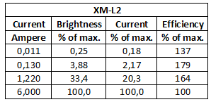
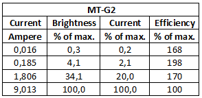
Anyway, numbers from HKJ test speak for themselves:
Actually if you do the math,linear drivers have similar overall efficiency in 1S 1xLED setups,so "90% better" than linear drivers can't be correct. And if you add the fact that most buck drivers are PWM CC regulated,total lm/W efficiency is worse than linear PWM-less CC (we're talking about high current drivers here). In 1S setups,only PWM-less regulated buck would have a little bit more efficiency on lower modes,but buck drivers have higher internal resistance compared to DD/linear drivers, so max. current on high would be lower.
Please keep in mind context for all of those statements.
The context of all of those statements was in reference to a 2s+ cell setup and diver / overall efficiency only, it was not talking about LED efficiency.
The LD-2 is a fantastic driver, one I still think about emulating. In fact with the recent discovery of reasonably priced aluminum PCB’s I am really considering it as I think that would be exactly what a linear driver needs to work properly so it can get the heat out of the driver and into the flashlight as good as possible.
I have nothing against it as a driver and honestly I should not have singled it out, I just had no other examples of linear drivers to use as examples.
I am sorry for doing that and understand why you feel defensive of your design and work, both of which are great BTW and need no defending as many many people can testify.
This post was in no way saying that the LD-2 is anything but a great driver, it was simply using it as the only known example of a working linear driver in a flashlight.
Statement 1: Under 2S conditions any linear driver will need good heat sinking to work properly. The LD-2 is not worse then any other driver, it is simply the nature of the beast when burning off that much power.
For 1S setups it really doesn’t matter what type of driver you use, they will all be efficient and work well.
Statement 2: This was referring overall efficiency, as in total watts from the battery to lumens out the front. While the LED will indeed produce more lumens per watt (as I have preached many times) the driver will also burn off a lot of power as heat.
The end result is that the total lumens per watt as seen by the battery is not all that different between a PWM FET and a regulated liner driver.
Those tests have since been shown to not factor in the lower temperature of the LED IIRC when PWM and just assumed that the LED would be lineally effected by the PWM which doesn’t seem to be the case. So the gains from true regulation are not as great as I once thought them to be. True regulation is still more efficiency, just not as much as was first assumed.
I plan to do my own testing at some point to see for myself the real differences, right now I am going on others data.
Statement 3: Once again this is based 2s setups but regardless the point is that buck drivers have very little heat compared to linear drivers. 100% of the “regulation voltage” turns to heat in a linear driver. In a buck driver only 10-20% of the “regulation voltage” turns to heat. Thus it is 80-90% more efficient.
The buck drivers I am talking about are true buck regulators that are now PWM.
In closing like many times the confusion boils down to context and details.
For example it is easy to confuse LED efficiency, driver efficiency and overall efficiency. It is also hard to point out exactly which one is being talked about each time you mention it, I am guilty of this as well. It is so wordy to always point out what you are talking about.
I thought the data easyb showed recently was pretty compelling for linear being impressively (to me) more efficient at low levels. Sure it's all relative. I don't get the statements about linear being less efficient at 2S though. All the voltage and power ratios should be exactly the same at 2S as 1S. Of course, there can be more power at 2S (but there's no strong reason there should be), and thus more heat, but I don't see why there's any less efficiency.
Power is just VI and efficiency in either case is Vou*I/(Vin*I) = V_out/V_in which is the same at 1S as it is at 2S. And for the same two batteries and leds, if wired in 2S instead of one, I is probably twice lower anyway of course.
Definitely linear is going to put more of the loss (heat) in the driver where PWM puts more in the LED. I'd think in the driver is better. It's been pretty well shown that heat reduces lumen output. I guess driver boards just aren't sinked as well though.
I am not sure where I said that PWM is less efficient at 2S? Linear drivers would be due to burning off more voltage overhead.
Yes, a linear driver will make the LED more efficiency and the whole setup as well. But not nearly as much as we once thought, which is why I said it would not be a big gain over PWM, it would be on the order of less then 10% IIRC in the overall lumen per watt from the battery. I have not tested this myself to know for sure though.
I was talking about linear drivers. I get your point about it not being amazingly better. Anyway, yeah, linear at 2S is 8.4/7.4 efficient at 3.7V Vf and linear at 1S is 4.2/3.7. In other words... exactly equal. For two leds and two batteries you'll be running them at the same current per led and same system efficiency too. Only difference is 2S will have less losses in contact/trace resistances, which really doesn't even matter since it's just less resistance for the linear regulator to create. It's still 8.4/7.4 even with all that. Linear is linear.
I think I was talking about total losses and the linear driver producing more total heat at 2s. Although like I said not sure where that exact quote is from.