I haven’t done a spring bypass on any light yet… and someone reported a 1k lumen increase on the Q8. That seems a lot! Would it mean the springs have a lot of resistance on the Q8? Would other springs be more appropriate…? Just a noob moder question. ![]()
If you are going to buy screws get some taps too. Cleaning the holes of anodize, glue and sand grit helps continuity. Tap will also thread the hole deeper if your screw is too long.
Other than going to a brass screw for better electrical path, the original screws are good enough if they have not been stripped. Mine were OK and I reused them.
Also keep in mind a brass screw is going to be even softer than the originals.
If I desired a “Quality” fastener I certainly would not buy from ebay, Alixp or BG. Places like Fastenal, Mr.Metric, boltdepot sell fasteners that meet industry standards like DIN (something) JIS etc. Go that route and spend the little extra money to do it and you prolly will not find anything under 100pc per size needed. Sell off kits of quality hardware to others. IMO its not worth the time and shipping to do it in order to recoup a $15 order on 300 screws. If you have a Fastenal nearby you can order special (non-stock) fasteners and have them shipped to store for pickup. I have also found Fastenal will sell small quantity of certain items but why buy 5-10 priced each when you can get 100 for the same price.
Aerospace or Military standards grade screws to hold a board in a flashlight? Really? Well you can triple the cost previously.
I already have better quality screws on hand that I could have used but because mine were Re-usable I reused them.
I soldered copper braid on the spring but instead of soldering to the battery PCB, I just made a hole in the center of the braid and screwed it in directly contacting the aluminum body, it bypasses the PCB and screw and just makes direct contact with the aluminum around the screw hole, I sanded, polished to a mirror shine and then used DeOxit and Progold on both the braid and the polished aluminum surface around the screw hole, I think is a more direct path for the current than through the screw…

AlexGT, excellent idea there. Simple and possibly the most effective end result.
If I get the desire to Re-Do my tail PCB mod I will do it your way. With slightly longer screws, possibly, if needed.
I'm quite disappointed with the dual spring results. I thought back on the BLF X6 (I think), there was marginal gain of bypass's over dual springs, but on the Q8 - much greater. Honestly, I could not get repeatable reliable readings on the stock Q8's. I think the drilling out the driver holes and using a round pan head improved the consistency, because a very hard tightening of the body tube was better than an moderate hard tightening, and the stress of threading thru the PCB and threading into the holes in the body are fighting each other, resulting in a distorted mount. The screws resulted in about 200 lumens boost for me, but the spring bypass's went thru the roof, form the 4% bump of screws to 25% to 30% about.
Stock light went from 4,800 (not very tight) to 6,400 (normal tightening) with the bypasses and screw replacements/cleaning/etc. The highest stock light read 5,400.
I dunno - djozz (I think) originally preferred to have a single high qual spring, and he was probably right. In the end, we didn't have much say or control over the springs - let it up to them over the last decision on them. It's probably not what we all wanted, but settled. I think the quality on the springs is not so good, and the inner ones are worthless - someone else mentioned that too. As I removed the inners on 5 Q8 tails, the bench was littered with gold glitter, on some the outer coating completely came off.
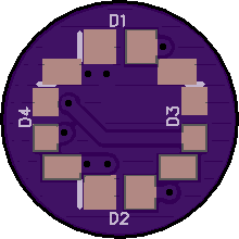
4 LED
You have to order 2OZ boards as they are only 0.9mm thick!
![]()
I daresay it is luck of the draw. If you are fortunate to already have good contact most way around the driver PCB ground ring, then there would probably be little more improvement to be had by drilling out the driver holes. But if, as others have reported, small amount of contact, only around one or both driver screws, that would suggest the screws are keeping that part of the driver slightly proud of the rest, so drilling out the holes would be the first thing to do, and it is so easy.
Screwing them out and in again may not make any difference, once self-tapped into the driver, they will go back in the same way next time. Unless you force it, and strip out the threading in the driver PCB, which is not really something to try.
Regarding spring bypass, yes, assuming these are plated steel springs (test with magnet), a bypass can make a huge difference, with a FET driver. Steel wire, long and thin (imagine your spring stretched out) is not great for conducting the current.
I would make the 4 LED footprints the same size, so you can buy LEDs the same size and put them where you want.
Thank you Lexel!
I would buy you a beer if i lived closer to you ![]()
The poor springs have an up-side, they will act as fuses (collapse) at excessive current levels , for those who e.g. put a cell in backwards.
Djozz was correct in preferring good springs, but some people need to be protected from themselves. Once you improve the tail yourself, you must take responsibility. Seems like a decent compromise.
Yeah!
YES! Thank you!
Keeps getting better.
As an aside, you can get silver (or silver-plated-copper) electrical braid too:
https://www.google.com/search?q=silver+electrical+braid
Turns out there’s an ASTM standard specification:
And hey, whaddaya know, there’s also a shear strength standard for nonferrous bolts:
https://www.google.com/search?q=ASTM+standard+metric+screw+electrical
I proved the fuse thing already 
 . Fortunately I got spare springs and no apparent harm done - to the light or cells. I had only 2 GA cells in at the time, one upside down - noticed no light blink or flash, then saw a nice little stream of smoke.... The springs turned blueish and collapsed - usual thing. I've seen this before.
I'd like to see I took one for the team and tried it, but...
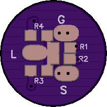
you could cut the traces and put there 0603 0 ohm resistors they also act like a fuse
its good to have 2 bigger pads
you can always reflow a 0603 on a 0805 pad
AlexGT, looks pretty darn direct, to me. Hey if it works for 1/24 scale slot cars (from the 60’s), it works for me.
Hmmm, maybe slot car contact braiding (ie., contact brushes) would be something to look into.

I now use the temp control and set it to a new tem. Worked like a charm! Thanks Tom and Lexel!!! But i have another question. I checked the datasheet from the VTC-6 and they can be discarged way below the 3,0V. Is there an option to set also the LVP levels?
Well, only in the code - there's a setting for that, but in reality, how many mAh are you gaining? If you look at it, not much is left below 3.0V. Some wanted to use a higher cutoff even.
The VTC-6 are going down to 2,0V. I do not know how many mAh i would gain if the cutoff is set to 2,5V but i have a heavy modded TN-31 and the cutoff there is set to 3,2V/cell. If i use the cells than in a light without LVP i got quite some extra runtime untill the cells are below 2,5V. So it would have been nice to be able to get this extra runtime by setting this cutoff via the modes. But so i have to wait for the next bigger mod (when i have the time to flash the mcu with changed values.
I will definitely ask you again how to when the time comes. So far i am really happy. And i am impressed how long it took to get to 60°C headtemp ~22A on turbo. That speakes for the design!
With the Luxeon V this time will be much shorter (@~35A :smiling_imp: )