Ok guys, this is the first time I’ve entered. And I’m going to start small (I have four small kids, so my only “work time” is after everyone is asleep and I can sneak off to the garage). In looking at past entries, even the idea in my head doesn’t hold a candle to the wonderful creations from years past. But alas, you have to start somewhere, right?
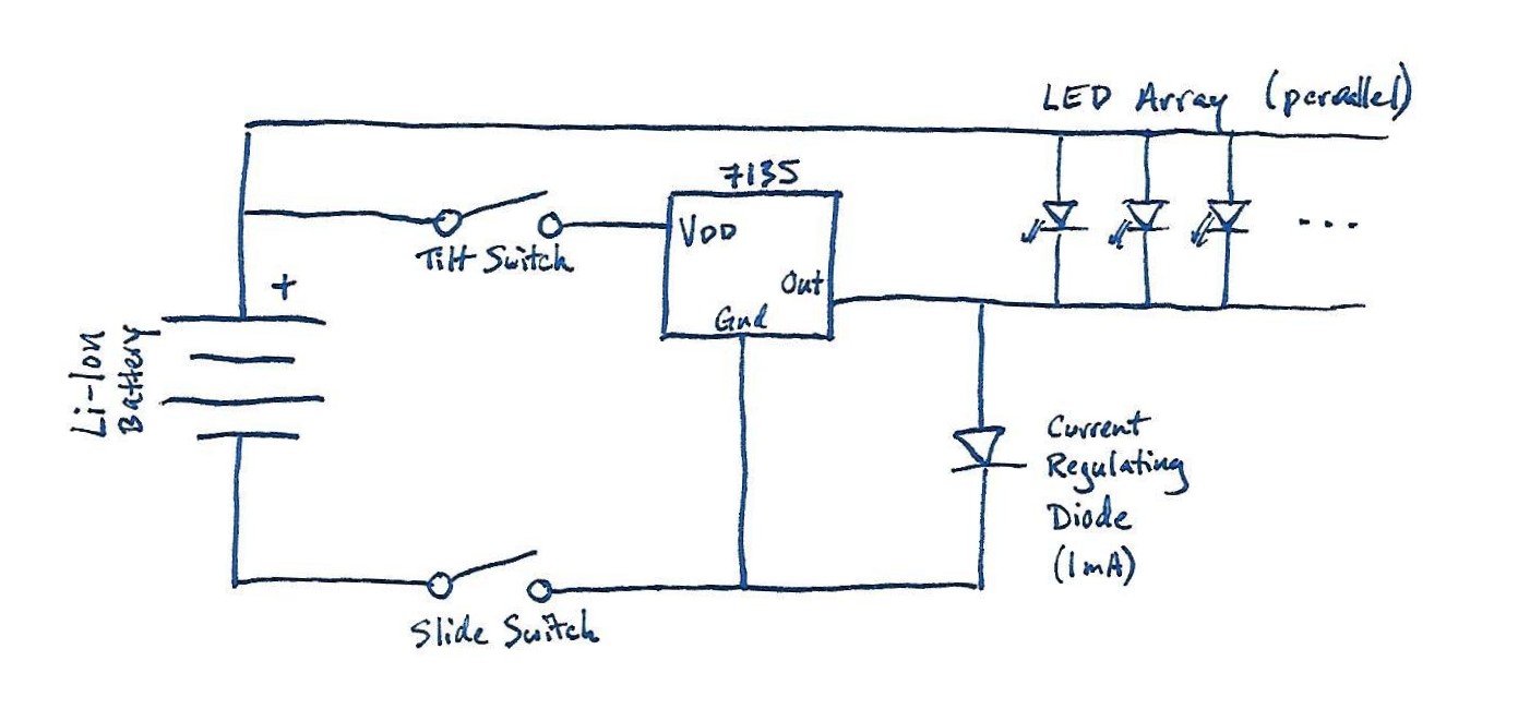
Behold, the flip-lantern! Well, at least a sketch of it.
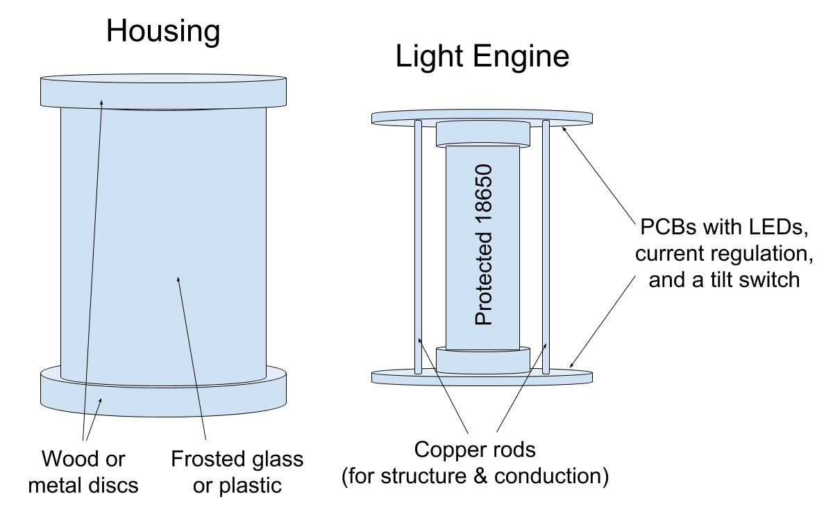
I’m thinking a small cylindrical housing of frosted glass or plastic (whatever item I can find of appropriate size) with flat caps of wood or metal at either end. A cap can be removed to access the “light engine” inside, which will likely be a sandwich of two custom PCBs held together by copper rods, holding a 18650 between them. The plan is for the PCBs to have 4x 80+ CRI 4000K 2835 LEDs on each one (8 total) being powered by a single 7135 for approximately 150 lumens. Also mounted on the PCB will be a mercury tilt switch and a LDO+resistor combo Current Regulating Diode (Semitec S-120T) to drive the LEDs at around 1mA when you flip the lantern upside down. Flip it back upright and the mercury switch will enable the 7135. Pretty basic, but it should be a fun first build.
Stay tuned!
.
Tasks Completed:
- Initial sketch done
- LEDs ordered
- Components (minus LEDs) received
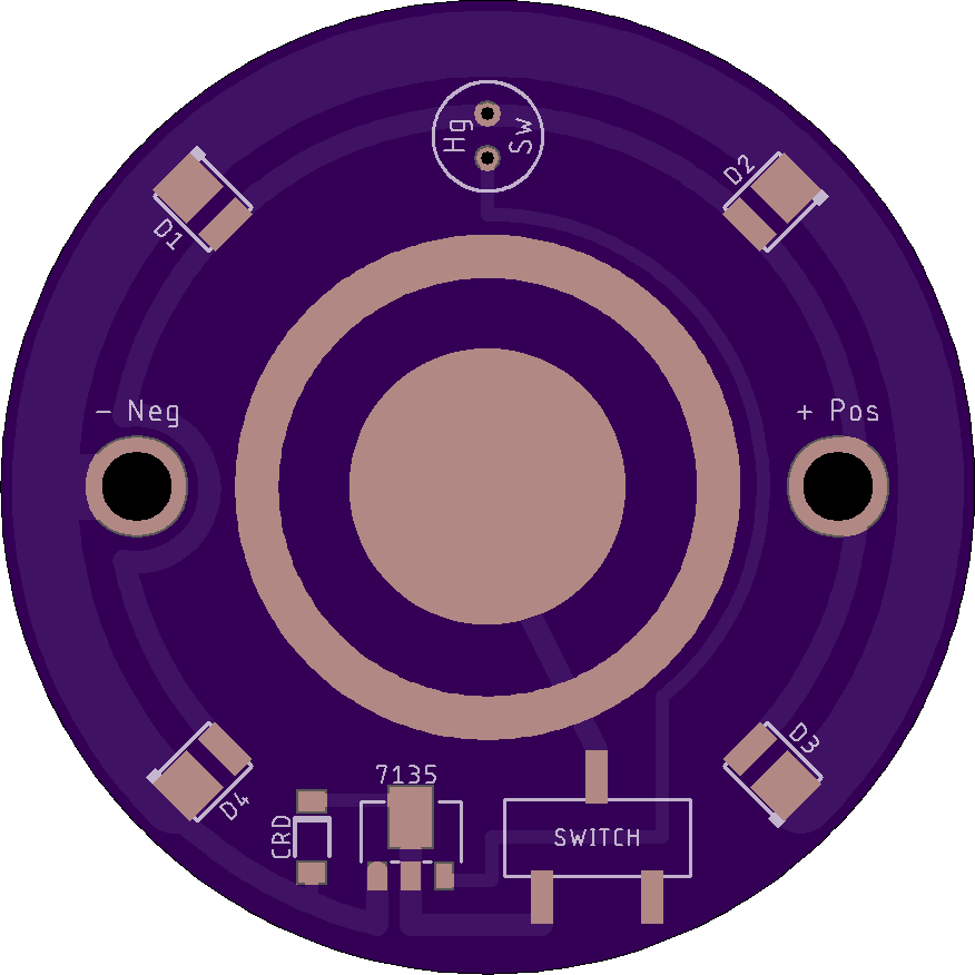
- PCBs received
- Housing completed
- Prototype built and tested
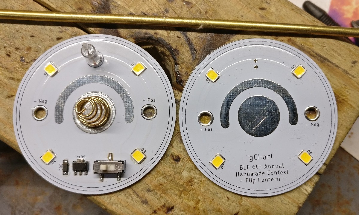
- Final PCBs have been populated
- Battery guard cut, sanded, and polished
- Solder battery guard in place
- Solder conducting rods in place
- Final touch-ups
.
Tasks In-Progress:
- Nada
.
Future Tasks:
- Nada
.
Final Pictures
PCBs before assembly
PCB labelling
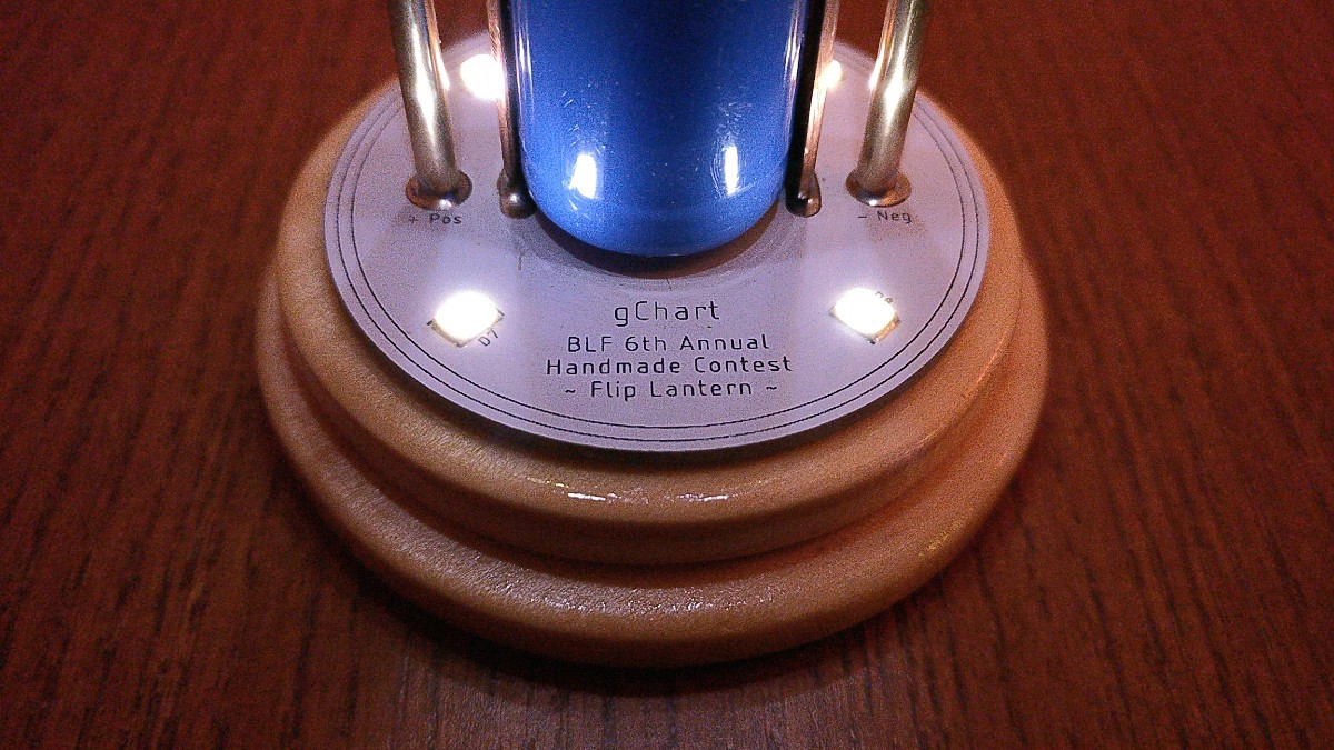
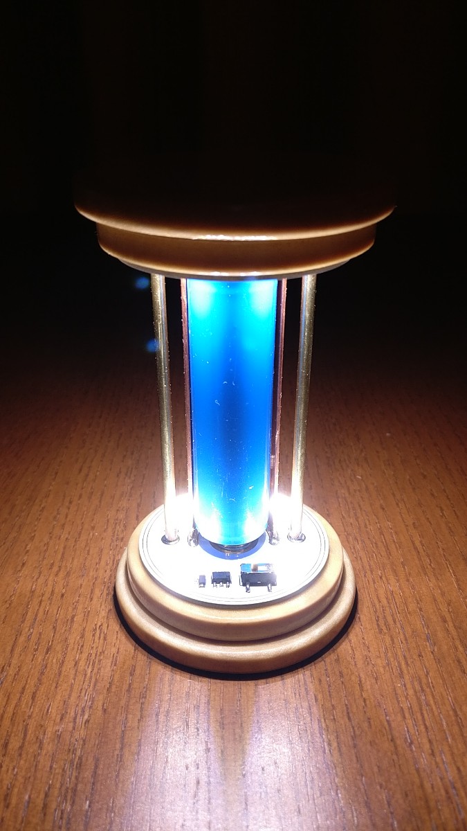
Internals, front
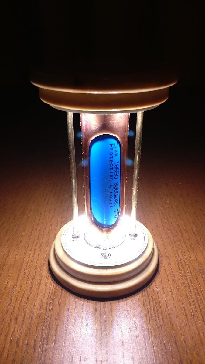
Internals, back
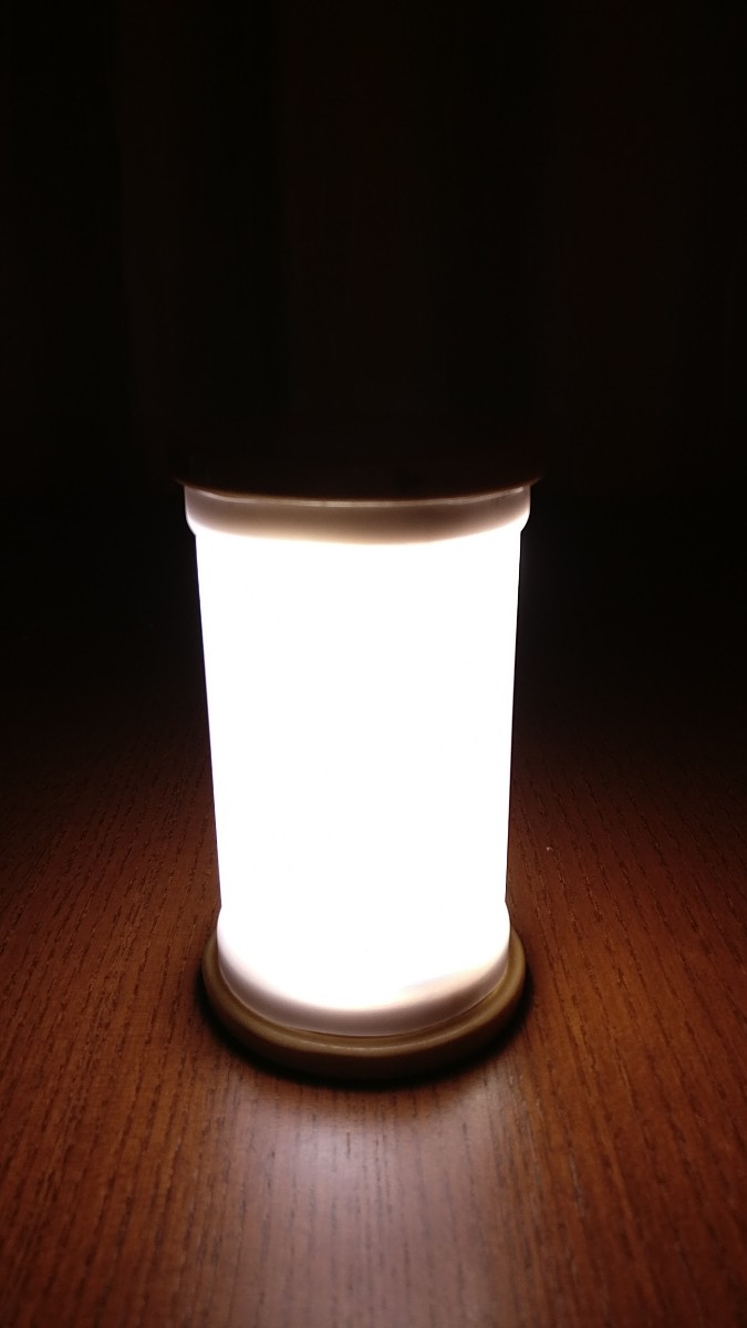
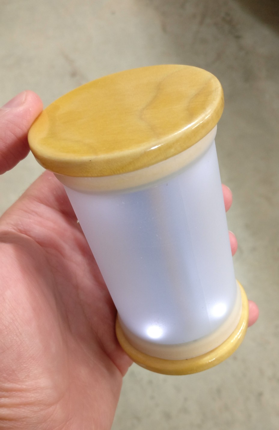
High power
Low power
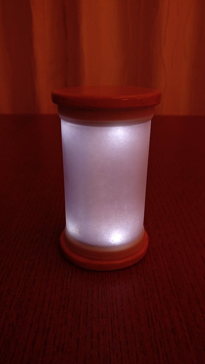
Here’s a proper shot of it, before the diffusion foam:
GIF animation
.
Highlights:
- Custom PCBs using white solder mask for reflection (Oshpark link)
- ~150 lumens from 8x 4000K 80-CRI 2835 LEDs (in High mode)
- On-off switch for traveling/storage
- Uses a mercury tilt switch to switch between High and Low modes
- High mode uses a single 7135 to driver 350 mA to the 8 LEDs
- Low mode uses a 1 mA Current Regulating Diode (Semitec S-120T) to deliver 1 mA to the 8 LEDs
- End caps are cut from a Poplar plank, shaped via sanding, and then polyurethaned
- Housing is plastic (cut from a seasoning shaker), roughed up with sandpaper, and sprayed with Frosted Glass spray. Additional diffusion provided by some sheet foam.
- Battery guard was cut from a 3/4” copper pipe and shaped with a drill, angle grinder, files, sand paper, and then Mother’s Mag Polish
- Connection between the two PCBs consists of two copper rods. This also provides a bit of structural integrity in addition to the battery guard.
PS - I have 6 extra PCBs from PCBway. I will likely never use them, so if anyone would like to build their own version of this, let me know and I could probably send you a set (sorry… US only, international shipping would be prohibitively expensive).