ok ,i add the link of spring here
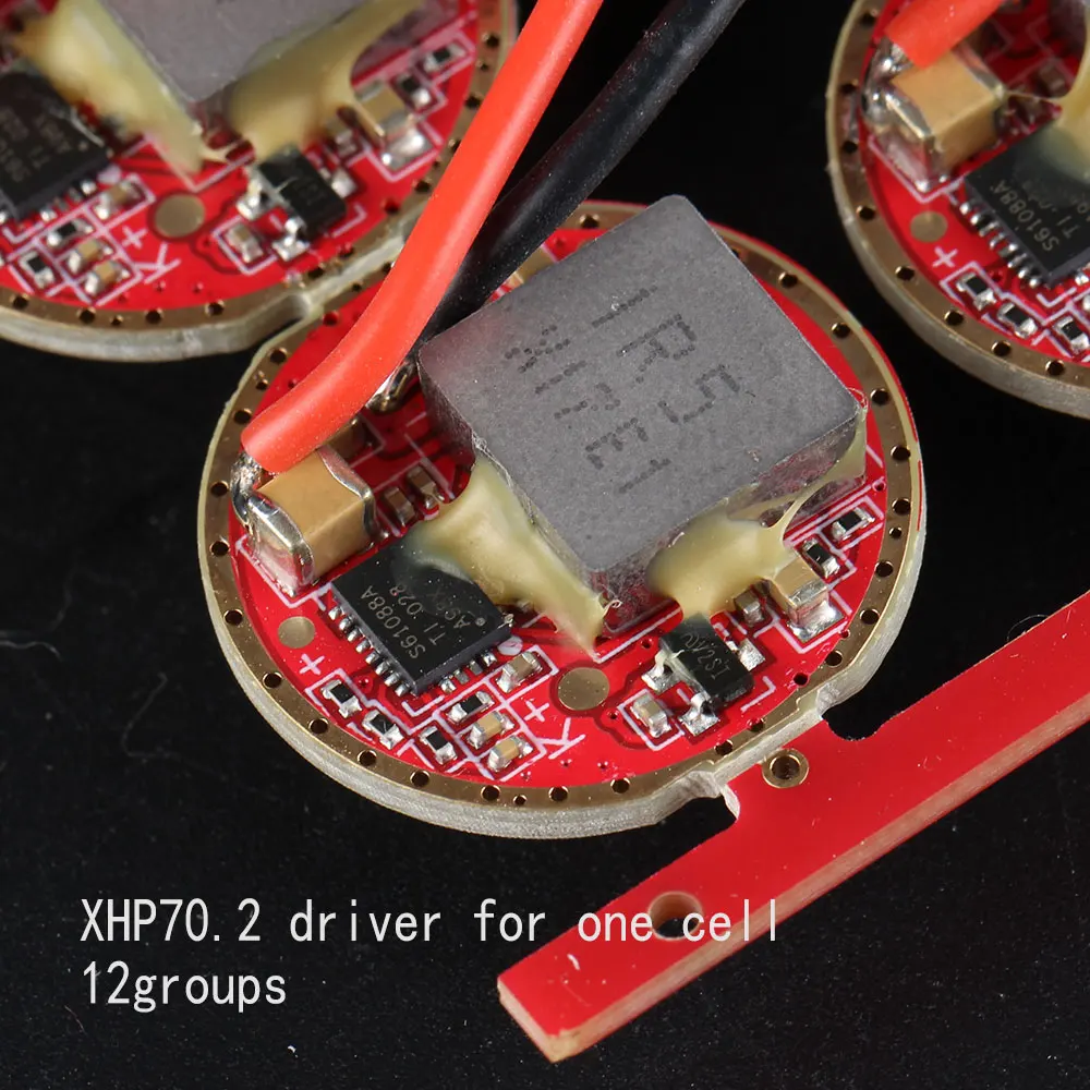
Simon, what is the diameter of the 12 groups xhp70.2 driver for one cell ?
I either can’t see for looking, or its not on the product page.
Yes, they use the same material, and the quality of the coated spring will be better.
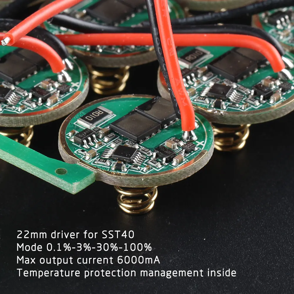
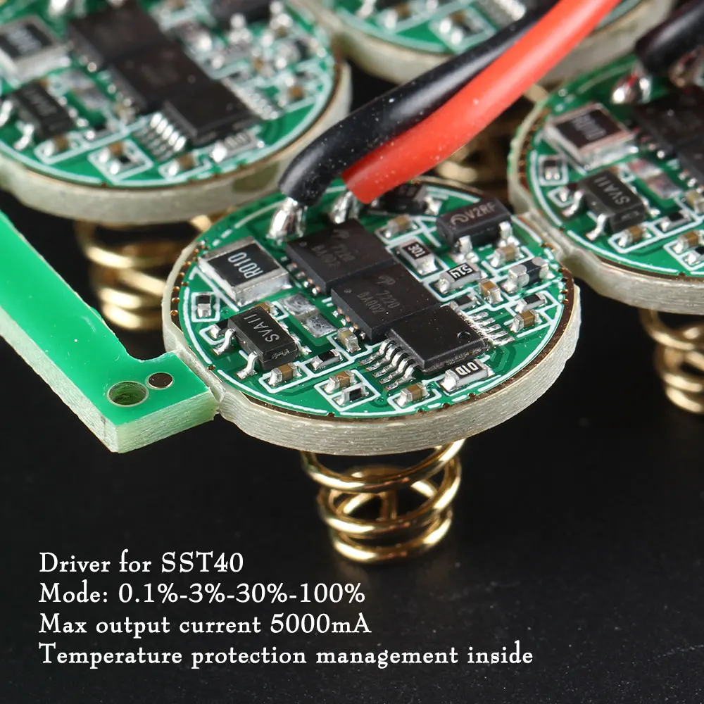
22mm
I have a couple things to complain.
The first one is personal and minor, I purchased and received an M2 host from Simon recently and finally got to build a torch with it. A problem I found is that the holes for the driver/emitter wires were not in the right place for MCPCBs from Kaidomain, and I've been forced to mill my CSLNM1.TG emitter MCPCB from Kaidomain for it to fit. Now I realize that the KDLITKER MCPCBs are not using standard 60° hole spacing. There was a tiny misalignment, though.
I also found that, after screwing down the bolts, they started topping at the outer black rim in the M2 cavity before pressing down the MCPCB. I added some Stars-922 thermal glue around the bolts to sort of fix this, and also ended up screwing them down as much as I could. Still I wonder if this is normal… :???:
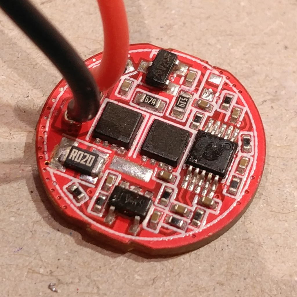
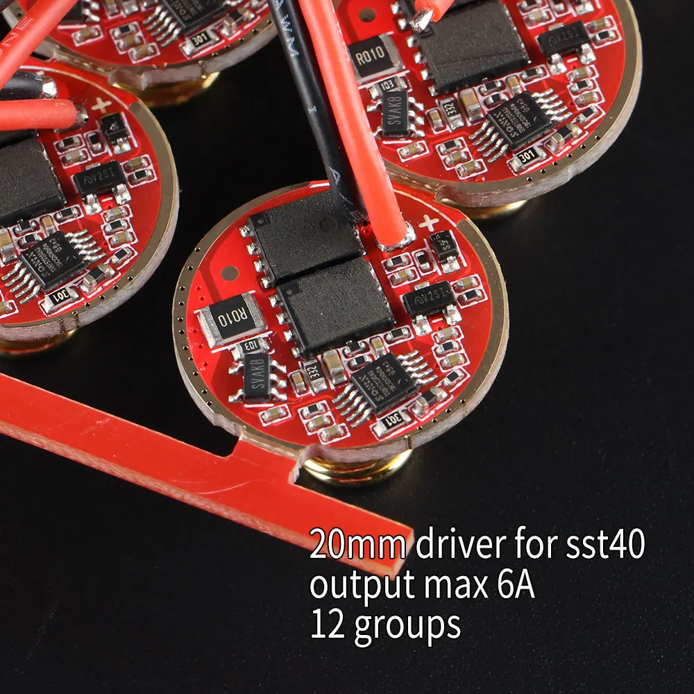
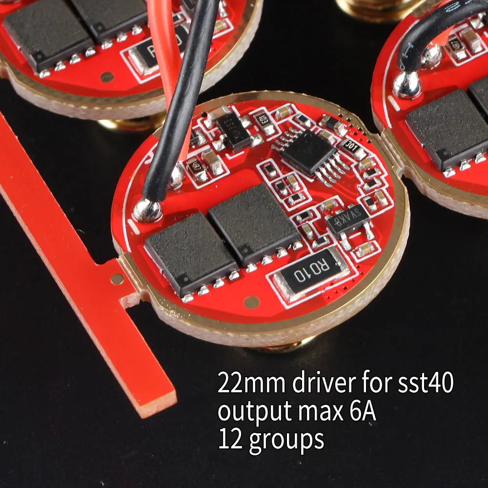
The other issue is related to the newer design of the SST-40 linear drivers. As you can see in the left photo, drivers do not have an electrically conducting outer track on the upper side. This, combined with the shape of the retaining ring in the M2, results in the driver hardly or not making electrical contact with the flashlight body. I also wonder about the thermal transfer due to the absence of the upper side outer track (solder mask covered).
I feel pretty dissappointed right now. I've spent a good deal of hours with this because at first I couldn't realize the driver thing was the problem. I think I could fix the problem by tucking solder paste on the bottom side outer track, and applying heat with my hot air gun. But I have mixed feelings about all of this, suffice to say.
Wed, 05/27/2020 - 07:37
Is this the driver you were talking about? Could I write my own code/put a modified crescendo onto it (as it has an atny13a chip)?
I’m looking for a 17mm driver that I can flash something with a super long pause beacon mode onto. Something like .5s on, 6 secs off
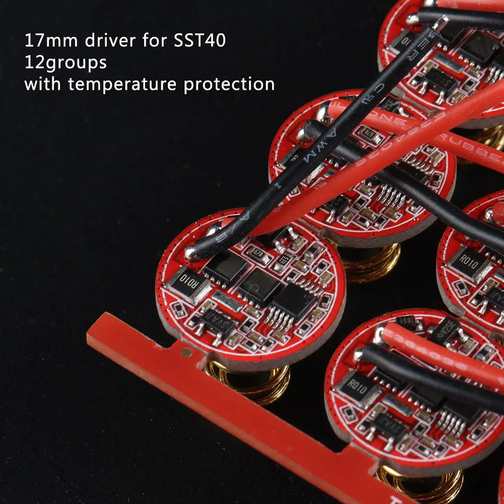
I noticed the same on the 17mm driver as well. No contact ring on the back of the driver. I wonder if that causes issues?
Yes.
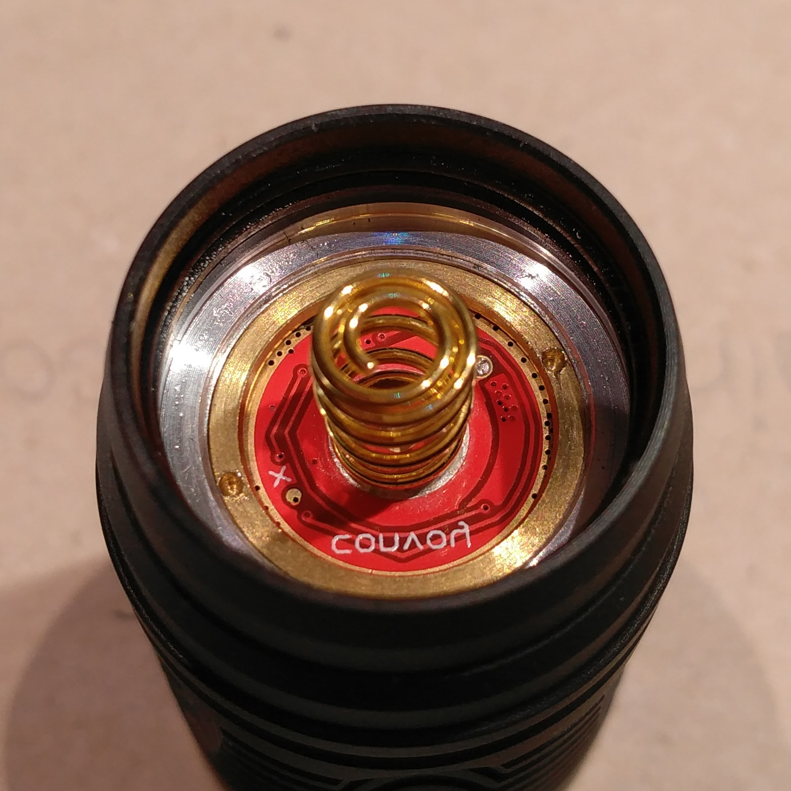
The missing contact ring track or ground ring track is that in the driver's front or upper side, at least as far as I know or understand these things. The back or bottom side is where the spring dwells.
I have a couple drivers and as you can see in my picture, I removed the NTC thermistors.
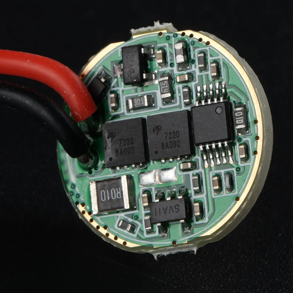
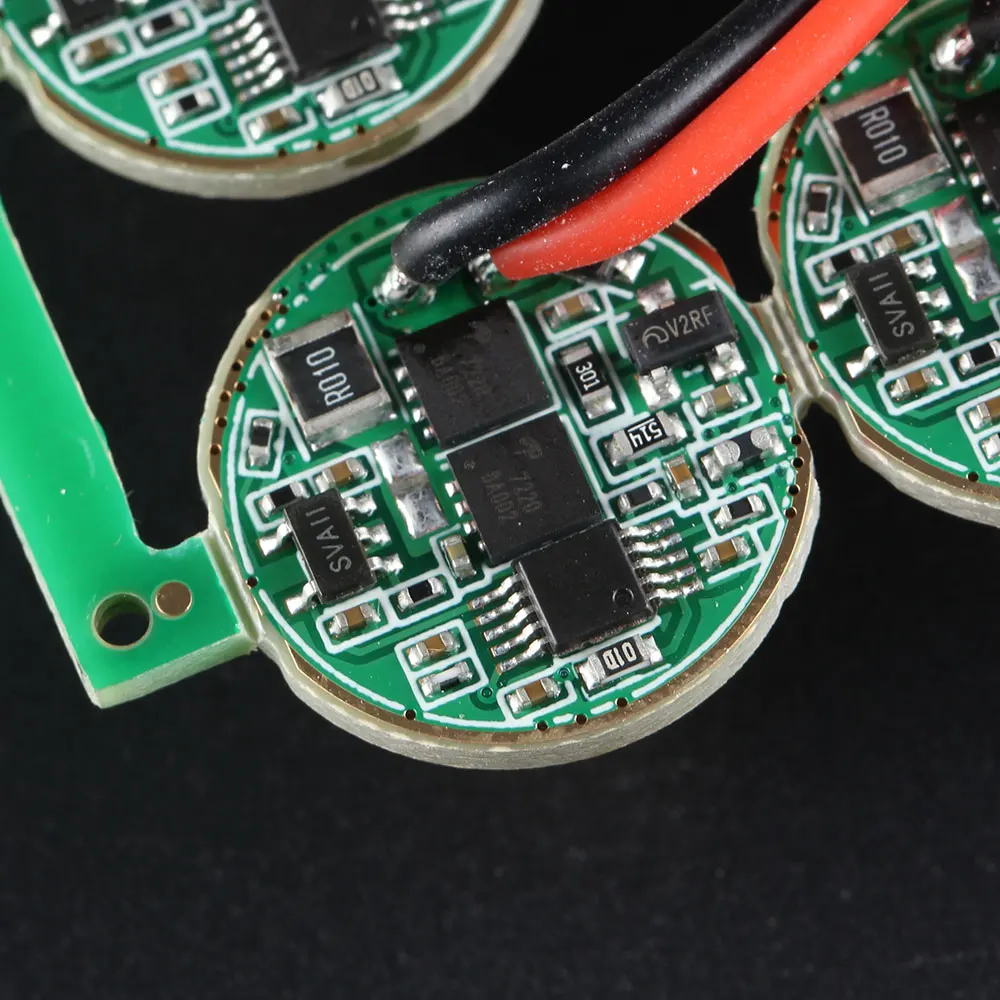
Notice the presence of an outer ground ring track in the green solder masked 4-mode drivers.
Without temperature protection I can only rely on good thermal transfer for my driver to work properly. But these drivers don't have upper or component side ground ring so, unless I am missing something, their life is gonna be rather short because of overheating. :???:
I am feeling rather uncomfortable at this right now.
Wed, 05/27/2020 - 13:02
Still, I have to come back and pinpoint this. My M2 build cannot work this way. The retaining ring has a sloped inner surface ring on the side which is in contact with the driver, and a small flat outer surface ring (which makes no contact with the driver unless I were to forcefully slip it). As it is, I can only make it work reliably by soldering the retaining ring to the driver. And I defitively don't want to resort to that!
Will wait for Simon to see what he has to say. I think I'll have to order a set of 4-mode drivers (drivers with a working, solder mask free outer ground ring in the component side), which even if I get some refund is going to be :(( another long wait.
Wed, 05/27/2020 - 15:16
Is it possible to use by flip’n the retaining ring over, file 2 slots in it for tightening with needle nose pliers. I have wire gauge drills that in this case I would just drill thru the holes in the retaining ring, deburr and use the other side of the ring…
I tried this with my C8 when I got the new “biscotti” driver. It didn’t work with the retainer the right side, so I flipped it and got the light to work for a few seconds then it killed the led and smoked the driver…something wasn’t happy with the setup! Maybe a short? I never figured out what happened.
Great... i’ve order several of these drivers in 17, 20 and 22mm.
Just great they don’t work...:(
I ordered 4 drivers, they have not arrived yet.
I’m alarmed by the conclusions of some colleagues, but let's not panic ahead of time. I would like to see Mr. Simon's answer. If a persistent problem is discovered, a solution will be found, I am sure. In any case, you are in a better situation than me, you at least understand the reasons, and how to fix it)
Hum, I know Simon will have an answer or a solution for this situation for sure!
But, the driver structure seems, indeed, strange.
Let’s try going bakwards: was that driver - with the same structure (meaning, no contact on the upper side) - originally used in any flashlight “ready to buy” from Simon?
Or was it made as it is for us moddersn, to try to fit it in “any” flashlight taking a 17mm driver?
Could it be someting related to those adapter rings that Simon sells to make smaller diameter drivers fit flashlights with larger driver diameter holes? https://www.aliexpress.com/item/33023608406.html
EDIT: I am not sure if my assumption is correct, but these adapters, are sold for 2 specific lights (M21A and S21A) that use the SST40 Leds, the one for which this driver is suitable/designed for.
As the adpaters have an upper ring, that will make contact both with the lower ring (and the bottom of the driver), and the pill, maybe they can replace that contact edge of the driver.
Hence, it seems to me that this may be the reason why these drivers have that design, to be used in those 2 specific flashlights, with those adapters!
But I may be wrong ![]()
I think these adapters were out before this driver
I think this is a problem related to the driver manufacturer. If you look at the driver advertisement pictures, the only driver which has a solder mask covered upper ground ring track is the ∅17mm version with 12 groups firmware:

https://www.aliexpress.com/item/33024201368.html
https://www.aliexpress.com/item/4000961062843.html
https://www.aliexpress.com/item/33024197621.html
https://www.aliexpress.com/item/4000961148004.html

https://www.aliexpress.com/item/4001003502544.html
https://www.aliexpress.com/item/4001050636235.html
https://www.aliexpress.com/item/33007449093.html
https://www.aliexpress.com/item/4000879891929.html
Blunder? A nasty one I'd say. :facepalm:
Now I wonder, is there some way to remove the solder mask without damaging the copper track? I wonder if scraping with some plastic tool… ![]()
Oh no, I have one of the those new drivers arriving imminently.
Sure, scraping off solder mask is easy, I scrape with a scalpel. May take 10 minutes to work your way around.
The 17mm was the one I got that was missing the contact ring. It died in my C8 with the retaining ring. I have another one on order…been in limbo for over a month over the Pacific somewhere. I hope Sim9n has a solution.