Hello. I want to present my latest project – the extended driver 3.0.
This solution is based on two components: standard driver board (17 / 22mm) and a special MCPCB substrate, which, in addition to the diode / LEDs also cases the driver executive element - MOSFET transistor. This solution considerably improves cooling so that all elements in the flashlight that emit heat do not cause the effect of artificial heating of the controller board through electric current stabilizing element.
This problem is common in linear controllers based on current stabilization by a FET transistor. Not only does the board heat up from the working LED, but also it receives a lot of heat from the operating current transistor.
This situation often results in discrepancies in temperature readings by temperature monitoring mechanisms. This is due to temperature sensors in the driver (in the processor or in an external element) heating up too quickly, which directly results in the reduction of the flashlight power. All this while the case is still relatively cool.
The power used on the transistor depends on the current flowing in the circuit and on the excess voltage it must break in order to stabilize this value. From a simple equation for power P = I * U, knowing the value of: supply voltage, current flowing in the diode circuit, Vf of the diode for a given current value, you can easily calculate the loss of power in the transistor and how easy it is to exceed the acceptable value … And here we have the solution to the puzzle: why in Chinese FET controllers the modes are usually: Low , Medium maximum around 30% (usually in practice it is less, ~ 20%) and very high value HI. Unfortunately, this element is very impractical when it comes to cooling. Its thermal pad is usually a drain and it must be electrically insulated from the case. Ok, but enough about boring things, let move back on to the subject.
In the presented driver, it isn’t a modulated PWM signal that provides LED supply current but it is done by regulated direct current. This has a number of advantages such as:
-the use of higher efficiency lm / W LED powered by low direct current,
-longer battery life (we take a constant value and do not tire it with high current peaks),
-it often results in no audible PWM signal,
-the flashlight does not interfere with other devices working in the vicinity (e.g. wireless bicycle counters).
The controller is based on the Atiiny25 processor, which through a very precise operational amplifier, controls the opening of the MOSFET transistor. The current is measured on a resistor of a very low value (5mΩ). The processor applies a current to the operational amplifier input. The signal from the measuring resistor is delivered to the second input. The amplifier turns these two voltages into a transistor control signal in such a way so as to maintain a constant diode current.
Functionally, the new version of the driver is similar to the extended 2.0 driver described below:
I am not a big fan of fireworks, n-clicks and any other complications of already simple and proven solutions.
So we have:
Three groups of modes switched between each other (4-mode EDC, 3-mode BICYCLE, 2-mode TACTICAL) - each mode in it can be freely programmed from among 16 brightness levels available during the programming process.
Default / factory mode settings in individual groups:
EDC: 0.2% / 5% / 33% / 100%
Bicycle: 7% / 45% / 100%
Tactical: 8% / 100%
Functional clicks:
1-click: switch to the next mode in loop
2-click: switch to the previous mode in loop
3-click: strobe mode with the intensity of the mode from which we called it (different operating frequencies depending on the group we are in: 4Hz EDC group, 2Hz bicycle, 16Hz in the tactical group - in this group the intensity is always 100%).
4-click: Precise measurement of voltage under load - the controller informs us about the tenth of V after 3.X. E.g. 8 flashes is 3.8V; 5 flashes are 3.5V etc. The range is from 0-10 where 10 indicates 4.0V (the battery cell just unplugged from the charger), while no flash (3.0V) means that in a moment you will be receiving a low voltage level warning. This way of measuring proves correct in diagnosing new lamps and an associated drop of voltage in the whole construction (a contact quality, etc.), since we are given the information which physical voltage is found on the driver level.
5-click: change the mode group EDC->Bicycle-Tactical
Configuration clicks:
6-click: Programming a given mode from a palette of 16 available brightness levels. While being in the mode we wish to change. Displaying the sequence occurs in the lowest mode upwards. Every mode displays for about 1,5 of a second. After reaching 100% there’s one twinkle, then it displays modes downwards. The mode is programmed during the display invoked by a click or by the mechanism of turning off the switch. If we cease to do anything during the procedure of presenting modes upwards and downwards, the light brightness will remain as previously set.
7-click: Disable / enable the memory of the last mode used
8-click: Factory settings reset: Default modes for all groups including moving to EDC group and turning on the memory. Does not reset thermal settings.
10-click: Increasing the temperature protection threshold by 5 * C
12-click: Lowering the temperature protection threshold by 5 * C
The low battery cell voltage warning starts when the cell, in a working mode reaches about 2,9-3,0V. Then a single flash appears and a reduction to another, lower level from the programmable modes palette (we reach ~2,9V in the given mode, and after a flash, we drop to another, lower mode)
Temperature monitoring
This procedure always works in the background and monitors current driver temperature. It is based on a Attiny25 processor internal temperature sensor . After reaching safety threshold (default 60*C) the driver flawlessly reduces power, then tries to equalize to the set work mode. If the heat isn’t effectively absorbed, next reduction occurs while holding to the preset safety threshold. After cooling the lamp (for instance, cool air blow around the lamp case) the face value returns for the programmed mode.
According to my guidelines, my friend Pyra is the codemaker of this project.
I have a problem to display pictures so only links below
Below is a table of programmable driver modes for the SST-40 bin N5 diode powered by Li-Ion 21700 Samsung 5000mAh cell:

Programmable table modes table for the 4x SST-20 bin L4 / 4x Luxeon V2 bin Y module (the values are practically identical, so I standardized them to one table) power supply 21700 Samsung 5000mAh cell:

Mod Convoy S12 (4x SST-20 / 4x Luxeon V2) optics: medium and wide:


Mod S21A
4 optics: ref. OP, TIR spot (narrow), TIR medium, TIR wide, TIR elliptical bicycle.


Convoy M21A SMO


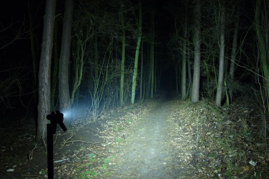
NIGHT SESSION:
Manual settings F / 4.5, exposure time 2.5 sec. ISO 200
As a reference FW3A 3x XP-L HI 6500K 900lm mode:

S12 4x SST-20 bin L4 5000K medium 100%

S12 4x SST-20 bin L4 5000K wide 100%

S12 4x Luxeon V2 bin Y 5000K medium 100%

S12 4x Luxeon V2 bin Y 5000K wide 100%

S21A SST-40 bin N5 5000K ref OP 100%

S21A SST-40 bin N5 5000K TIR spot 100%

S21A SST-40 bin N5 5000K TIR medium 100%

S21A SST-40 bin N5 5000K TIR wide 100%
S21A SST-40 bin N5 5000K TIR elliptical bicycle 100%

M21A SST-40 bin N5 5000K ref SMO 100%

 This is a pretty darn nice design. I'm very interested in 6A drivers for both clicky and e-switch lights. What's your plans?