Major, I have an HP Photosmart C4680 printer, scanner, copier. Will that work? Thanks for the links. I’ll watch them.
Texas, thanks, that’s the sort of detailed info that leads me on and helps me grow. Like a QB leading a receiver. I understand enough to reach for more. So you’re with Major and would reccommend learning to use Eagle?
Ledsmoke, I get so much info and entertainment from all the threads here, from the daily joke thread to the welcoming committee plus all of the fantastic mod work done that its nice to find a gap where I can tuck my shoulder in and push. It’s pretty slow going most of the time but that’s how I work. Read and learn up front, then apply and learn some more by doing.
I’ve loaded Eagle freeware onto my laptop and have read the tutorial from end to end. I’m taking it on faith that after 2 or 3(maybe 4 or 5) more read throughs it will start making sense. There are quite a number of terms that are not part of my vocabulary and it will take a while to burn in my organic eprom. While its possible to make a pcb with a pen, in order to get the board size I want I’ll need to learn some kind of software to generate the narrow traces and ic footprints needed. Unless someone expresses an interest (or I get stuck) I will avoid posting the gory details and stick with pictures and short sentences like: Is there an Eagle for Dummies anywhere? And Why is there no glossary in the tutorial pdf. The circuit above is certainly not complicated so as soon as I get a handle on the toolbars and commands it should go quickly(dream on McDuff). :Sp
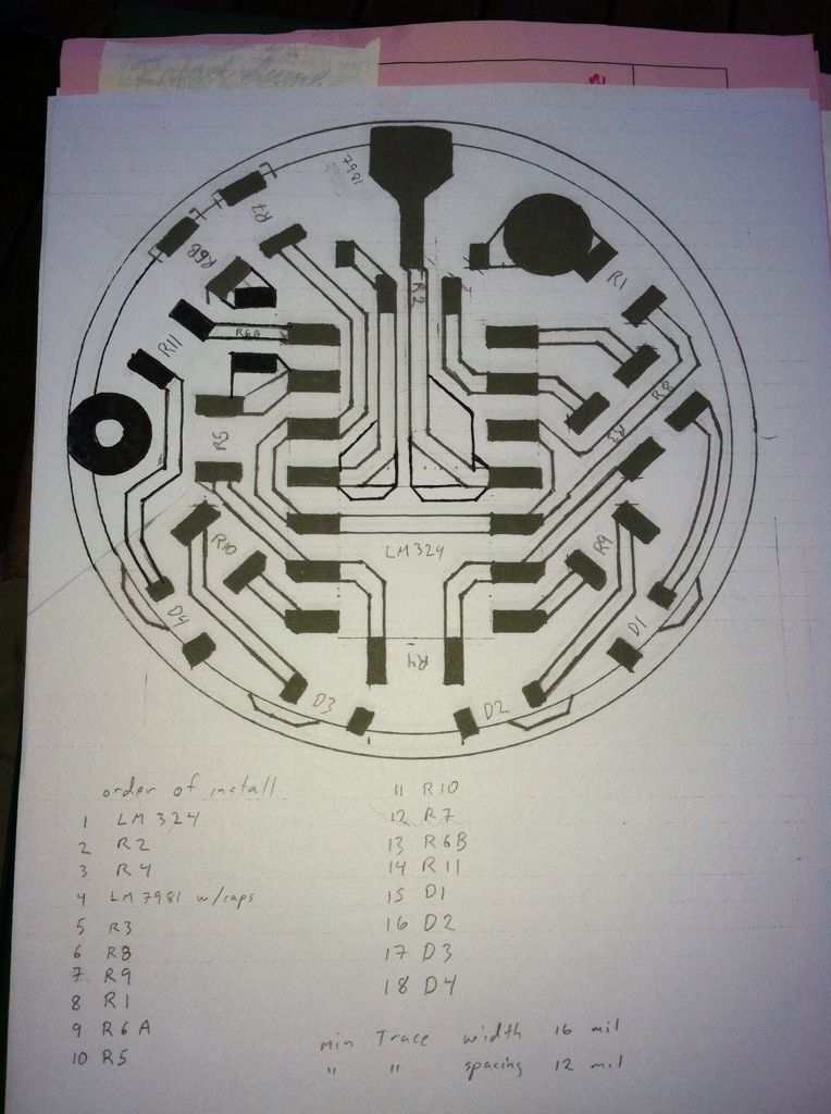
I’ve been sadly neglecting my homework with eagle however instead I drew it up the old fashioned way to see how the pieces would fit. I started by blowing up the scale by 10:1 and laying out the footprint of the quad op-amp and going from there. Right away it became obvious that I would have to use the resistors as jumpers to generate a one sided board. This is desirable so that I can stack this board on a 105C and put the battery spring on the bottom of this board. After dinner I will edit this post to include a picture of my artwork. I’m pretty certain that I will be using Oshpark to make the boards as my minimum trace width is 16 mil and the minimum spacing is 12mil and I’m not confident this can be done with photo resist and for the price it’s not worth trying. Maybe another board but not this one.
There are some extra lines in the middle where I decided to add copper to the input and ground traces. The Zener diode has been eliminated in favor of a 5 volt regulator chip and I’m using 1% resistors instead of a pot.
very inspiring! I may end up going a similar route for a wireless remote receiver if I can’t find what I want commercially. The 5V chip you mentioned - this is to provide the 5V power supply for the board, right? What’s the input voltage (higher, I’m guessing)? Getting the right voltage to a receiver from a 2S li-ion battery is proving quite a challenge.
Dr Jones was kind enough to clue me into the 7805 chip in my other thread 7135 drivers at higher voltages
It works from ~7V-30V and looks just like a 7135. For a 2s battery I’ll use a similar chip, the ld2981 which should work from 5.2V-16V. The dropout voltage is much lower (.2V@100mA-.007V@1mA) on the 2981 which allows it to work down to full discharge. The 7805 has a 2V overhead so it works with 3s or more. Both chips are available from Mouser but I bought the 7805’s off eBay. The 2981 also requires capacitors that the 7805 does not. They are available in different output voltages.
Making progress. I’ve managed to do the schematic capture part and now need to turn it into a board file. One neat thing about this design is only 2 resistors(R1&R6B , see paper pcb layout) need to change for different battery voltages. I think I’ll change the orientation of R6B to make it easier to access. I think I may increase board diameter to 17.5mm to give me room for I/O capacitors. This might give me room for a second ground ring via to better connect/support the pcb on the driver pcb. I’d remount the + spring on this pcb. The most current working idea is to set this board up so it stacks on a 105C board. The LEDs are in a 90 degree arc so would all be visible at the same time.
Stayed up into the wee hours plunking away. The good news is that the software seems to work properly. The bad news is that my soft tissue is slower on the uptake so I keep doing things over as I learn. I’d show the progress but I haven’t figured out how to copy the board file page. The 0805 solder pads are too large and I need to either resize them or create a new library device that has the size I want. I wonder if an 0805 jumper has smaller pads.
Though I don't completely follow what you are saying here I do understand that you are still making progress. Personally I'd love to learn about this but I figure that I'd never get to use it anyway. Already I never have any time for simple mods so this? Way beyond me. But when you get it to work it sure will be something else. I can't help but wondering how I might incorporate it into my beloved X7.... :-)
Although I’m not designing this to sell, I am trying to make it possible to add it to an existing light if anyone wants one. Hence the small diameter. Last year I spent way too much time on Sudoku puzzles and spider solitaire. This is much harder and I Learn something new as well. That OTHER mod, the one with 7135’s is ready to go. I’d like to have this ready before I actually build a light even though I already have an idea cooking: quad XTE or XPG on a 25mm Cutter board 2s2p from 2s 18500’s using a 105C with each side of the board pushing 1.2A to each pair all in a copper headed host. I need to finish before post #1000. What a mouthful. I just found out I need to create my own “library” chips in order to make all the solder pads fit on this penny sized board. 12 resistors, 4 LEDs, a quad opamp, and the VR chip. Single sided of course.