i forgot to mention, the battery i speak of is a LiPo, which the lower cut off is 3.2v, i know the 18650 batteries can be taking down further, but LiPo the low cut off should not be lower than 3.2, actually 3.8 should be the low discharge
Where did you heard such a thing, and what tells you that is correct?
3.2V can be used as a cut-off value, although it can be considered a little bit high, particularly for a BMS which must cut-off under load. 3.8V, though, is straight out wrong.
There is not that much of a difference between li-ion and li-polymer, and it certainly has nothing to do with the cut-off values you can use.
Check out lygte-info.dk. It is a site dedicated to tests of electronic devices and batteries. Henrik, the site's owner, has done hundreds of battery tests. He usually cuts-off at 2.8V for li-ion and 2V for LiFePO4, and the shape of the tests curves and the different rate of each discharge curve allows you to see the energy remaining for any given cut-off value (at or above 2.8V, that is). Examples:
/Samsung%20INR21700-50G%205000mAh%20(Green)-Capacity.png)
/LiitoKala%20INR26650-50A%205000mAh%20(Black)-Capacity.png)
This LiitoKala cell is actually manufactured by Power Long Battery (at first they started selling it to consumers in their original wraps).
Not much else to say. You can keep cutting off at 3.2V, but now you know (or you should) there is no problem if you go lower.
The way I believe and my experience tells me I am right. I rarely, if at all, need to replace a smartphone battery. And I keep my smartphones for many years, cycling their batteries well above a thousand cycles, or more. But 0 to 65%, as a rule. This means my smartphone battery (4.35V type battery right now) lays at ≈4V without load (i.e. the minimum load of the battery monitoring software and the smartphone while sleeping, tad less than 30mA or so) just after I stop the charging process. As I said, it's the high voltage or high state of charge what you must avoid if you want to ensure ultra long life for a li-ion (or li-poly) battery.
Hello fellows,
Very recently I had the “pleasure” of repairing a Dremel 3000 making use of one the above generic parts coming from AliExpress.
Let me show you a couple related pictures:
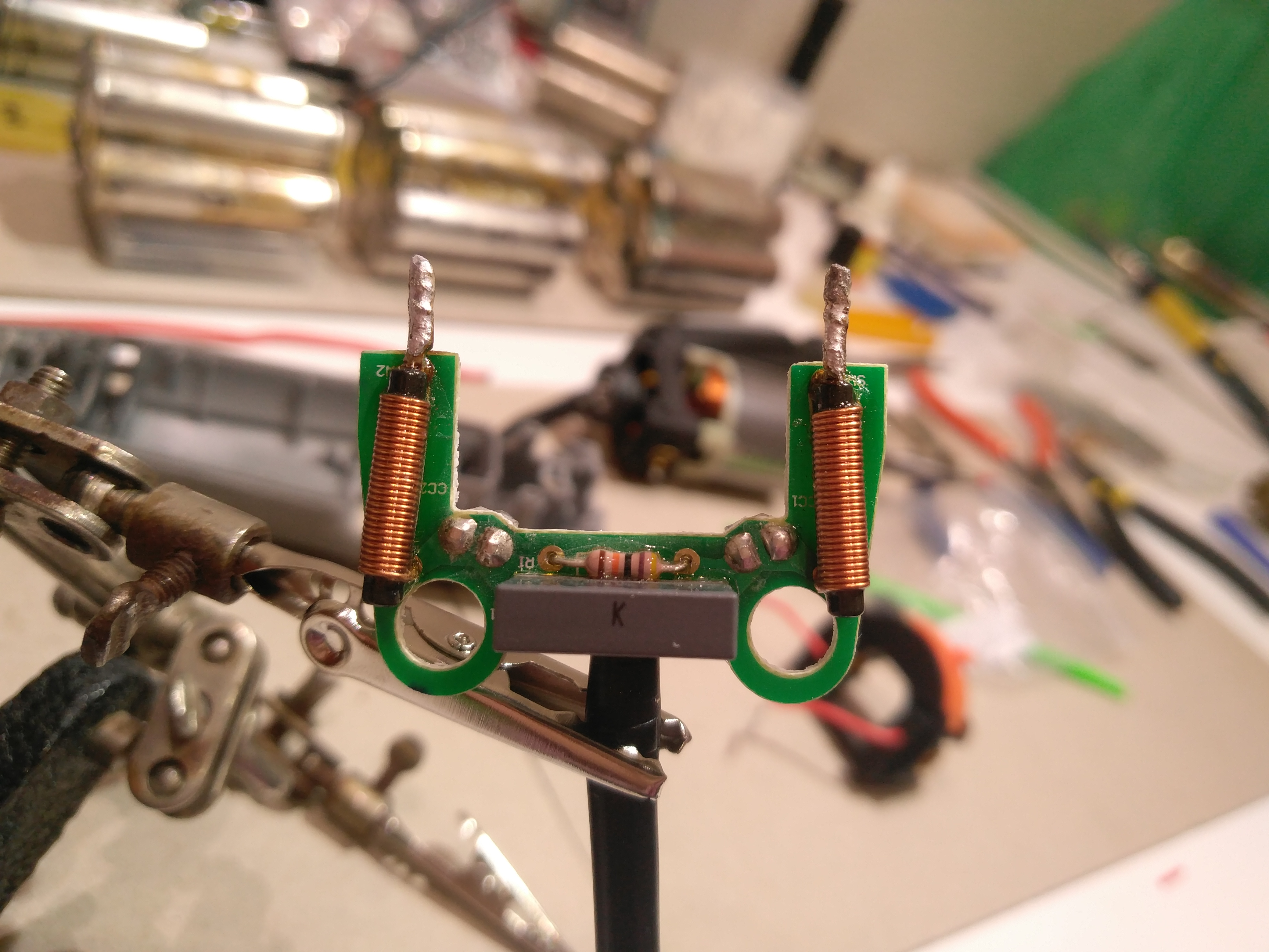
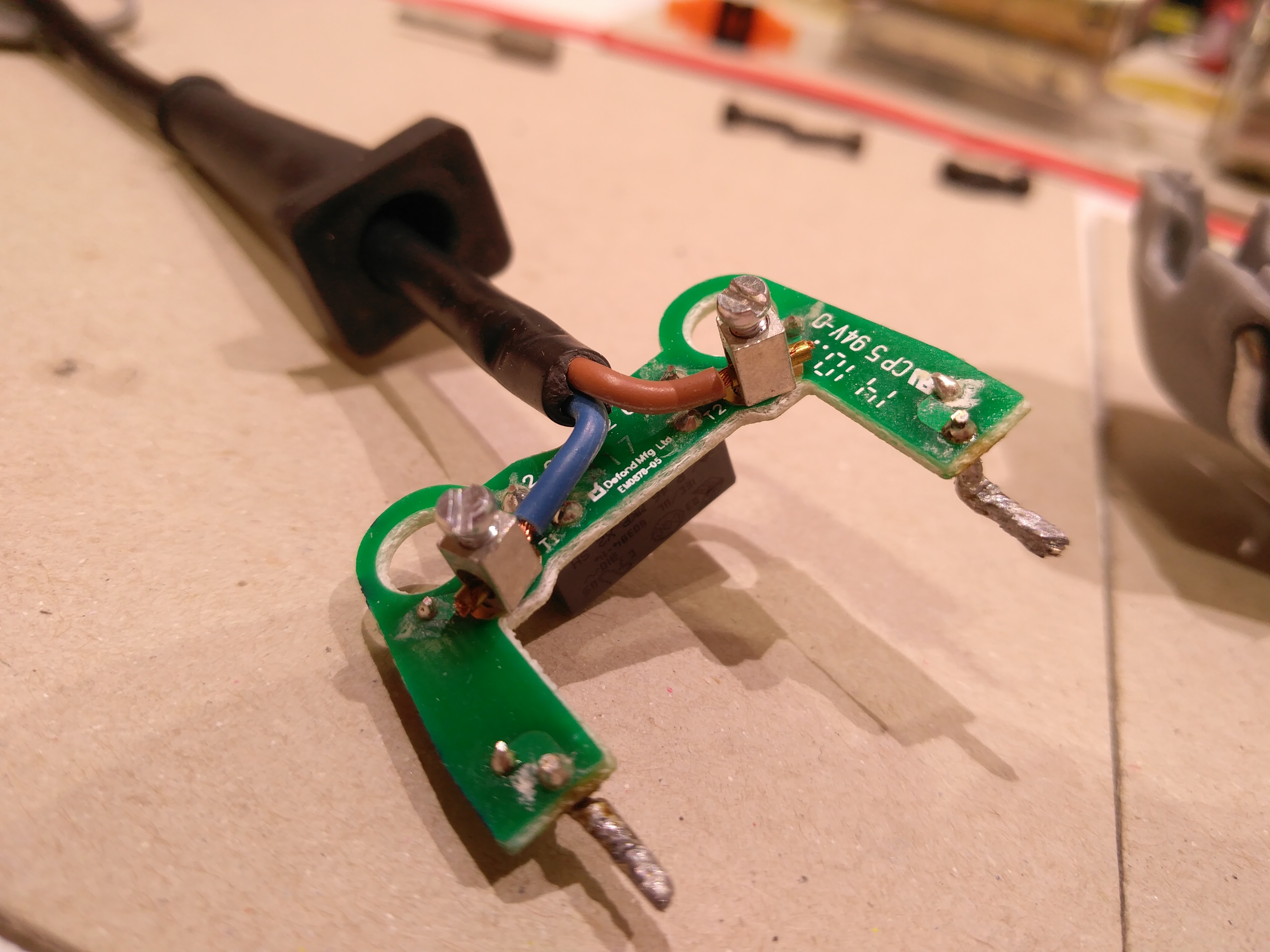
Note: ignore the thickened rods at the end of the coils, that is a modification I did because of reasons. They actually are much thinner, meant to insert inside holes at the original speed regulator.
I had a few words with thefreeman about this matter more or less recently, about the input coils you can see in the pictures. Nothing conclusive, though, I was then thinking that the purpose of the coils probably was to increase the power factor of the tool.
At this point though, I think their purpose is to reduce or eliminate the noise from the triac-based regulator, while I also do not discard the power factor benefit; I would love to hear more experienced fellows in these matters, though.
Here is a related thread: Power main distortion from TRIAC dimmers, what can I do to get rid of it?? @ EEVblog
And more:

Conclusions.-
The Dremel brand “gangsters” deliberately designed the speed controllers of their tools to break over time. After all, they are triac based and unsuitable for driving electric motors unless some sort of snubber circuit (?) is used. ![]()
But back to the mains distortion issue induced by these controllers, how do you experts think we could reduce or negate it? This is mentioned in the above aforesaid EEVblog thread. A couple of coils at the input and output, like in the above Dremel 3000? I wonder about the proper rating for the coils (amount of henries). Would stuff like these “5Pcs 10mH 4A Annular Common Mode Filter Inductor Choke Toroid 0.6 Wire 14x9x5mm” or these “5pcs toroidal common mode choke 9MH filter inductor 18x10x10mm magnetic ring” be of any adequate service?
Cheers :-)
Hello! :-)
I recently bought a couple of these dimmers, one of this kind and another one based in the BTA41-600B from here:

I was hoping to be able to measure the average output voltage of these “governors” with my cheap multimeter (this type) in AC voltmeter scale, but it doesn't works, all I see is ≈230VAC in the multimeter's screen no matter where the potentiometer is set at.
Any suggestions? Besides buying an :)) oscilloscope, that is.
Thanks and regards everyone.
Hi!
I had one (not your model posted) that didn’t dim, still at max even rotate the pot.
Then checking the TRIAC I found that was bypass, two of their pins were bridged on pcb traces by a solder blow.
Fixed this mistake now work properly, hope you can solve
Salvador, i think your dimmer may be broken.
i have a light dimmer like that which is always full ON no matter the setting of the dial. Maybe that is a default failure mode.
To see the gate control will likely require an oscope.
Best wishes and good luck sorting it out.
Thanks for the comments fellows.
I just tested the TRIACs in both modules using information from How to Test TRIAC with Multimeter @ Inst Tools. Long story short, the TRIACs work correctly both ways. When I connect the gate of the TRIAC to MT2 the diode voltage drop is very low, like ≈0.07V (compared to ≈0.45V for an old 3A rated 1N5404 diode I had lying around), but I guess this is pretty normal because these TRIACs are composed of two very beefy diodes. The first two digits in their “part numbers” (BTA16-600B and BTA41-600B) are their average maximum current ratings in amps.
Yeah but 0.07V forward diode drop sure seems like a shorted diode, just sayin’
I don't think they are shorted, I'm pretty sure they are working correctly. The thing is that the multimeter is pushing sub-mA currents through these massive, dozens of amps rating diodes, and so the Vf is super low at such current level. I have tiny diodes here and their displayed Vfs are way higher when tested with the multimeter.
Now, the answer to my question is here: Would analog multimeters measure correct dimmer's output? @ Electrical Engineering
In essence, my lame-ass cheap multimeter can't measure the average RMS output from the dimmers, as the waveform is far from senoidal. For this reason I am going to grab a proper analog AC voltmeter, Young Frankenstein :-)) style. Or I could also get one of those Voltcraft VC-155 multimeters. These will do the job properly.
I decided to solve this measuring challenge by buying an inexpensive analog multimeter here, “Samwa” ;-) brand. Guess it's sort of a copy from a “Sanwa YX-360TR”, sort of. I also found the following video:
 -SAMWA YX-360TR LED Test")
Wow! Compared to my digital multimeter that thing is huge. :-D
I decided to make a short video showing how to measure the output voltage of these dimmers (method of course also works for BTA41 based modules, tested it also):

Long story short, trying to measure their average output voltage without any significant load won't work.
Wellp, and I ended up ordering this MF47 analog meter the other day. Guess I like vintage stuff LoL.