AMC7135

What is the effect of having more or less of the AMC7135 chips?

What are the differences of the effects of having a config of 2800mA AMC7135x8, 2100mA AMC7135x6 or 1050mA AMC7135x3?
They are all using a single 18650 cell.

The light I saw at has different configs available and those I mentioned above has 2 groups and can be switched to 3 modes or 5 modes.

AMC7135 is a current regulator. It supplies 350mA per chip as long as the input and output voltage is within the specified range.

If a driver has 8 AMC7135 chips, it will supply constant 2800mA to the LED for as long as the battery can supply it.

If a driver has 6 AMC7135 chips, it will supply constant 2100mA to the LED for as long as the battery can supply it.

If a driver has 4 AMC7135 chips, it will supply constant 1400mA to the LED for as long as the battery can supply it.

etc.

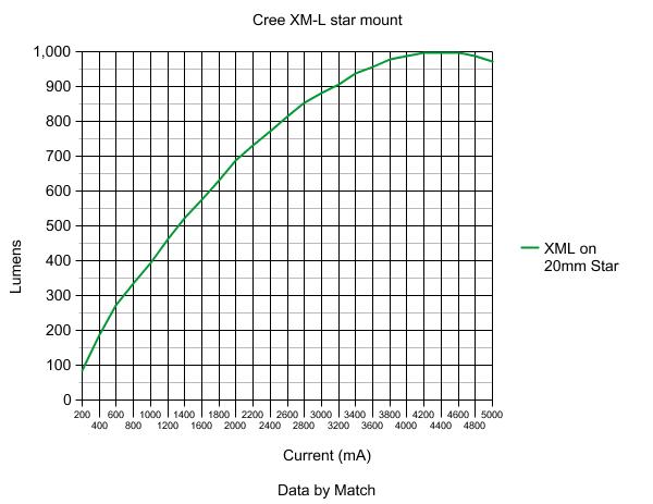
AMC7135 chips are current limiters. Each one allows 350mA. Thus, if you have 3, your LED will be given 1050mA.

To see how this relates to brightness, you can approximate by using this graph:

For more information, visit this link:

https://budgetlightforum.com/t/-/2346

Thanks for the info.

The light I am looking at has the configs with xml u2 led.

I had though the modes might be affected by the chips.

Does the qty of chips need to be even or odd numbered or is there an optimum number? is 8 the max on a board?
i looked at the brightness bins info, i think x8 of the chips will drive the xml u2 chip to max brightness?
http://flashlightwiki.com/Brightness_Bins
is 3000mA the limit for xml u2 or is it just a arbitrary number listed for the lumen values on that page?

so more chips is means more bright/heat with less runtime and less chips mean less bright/heat with more runtime?

Modes are not affected by quantity of chips.

Odd or even number of chips is irrelevant.

8 is the maximum to stay within Cree’s recommended current limit, but many people install more and have successful results. Heat will be your enemy.

Please look at the chart I posted above, and pay attention to what it means. Find your “happy spot” in relation to power consumption vs. lumens.

The higher you go, the less efficient your LED becomes.

BTW, thank you Match for your useful information.

According to the graph posted by ChiggerPepi:

To go from 800 lumens to 900 lumens (+12.5%) you need to go from 2550mA to 3200mA (25.5%), so: more current, less runtime, less efficiency , more heat, a bit more light.

If I run a light with 8x AMC7135 at 50% mode, would I get the same brightness and runtimes as a light with 4x AMC7135 at 100%?
using xml u2 on 1x 18650.

e.g. if someone is going to use a 4x AMC7135 at 100% most of the time, is it better to just get a 8x AMC7135 and run it at 50% to get the same brightness and runtimes but with the option of a higher hi with shorter runtimes and a low mode that is twice as bright as the low of 4x AMC7135?

It partly depends on the programming of the driver. Many 7135 based drivers use pulse width modulation to control the lower modes. The Chips turn on and off at high frequency. 50% means the led is fully driven but only on 50% if the time. Since the IC controls all of the chips, 50% of 8 Chips will be more current than 50% of 4 chips.

4x AMC7135 at 100% will be brighter than 8x AMC7135 at 50% PWM Duty Cycle

The difference in battery life will be insignificant.

Rufus, did you mean 50% of 8 chips will be more current than 100% of 4 chips?

Does it mean regardless of modes, I am better off getting a light with less chips if I want longer runtimes instead of using one with more chips at medium and low modes?

They would be essentially the same but this means a 10% low is still 300 mA on a 3A driver but only 150 mA on a 1.5 A driver. You need to be aware of this when shopping drivers. Low and medium are relative to the high for that driver. A 10% low mode on a 1.5A will give more run time than a 10% low mode on a 3A driver.

Perfectly stated and simple. I like it. (and correct, of course)

Is that because of losses in the additional chips?

No, it’s because of the fact that LED efficiency is inversely exponentially proportional to drive current.

Sorry to dig up an old thread.
“inversely exponentially proportional” is called logarithmic.

Nah, that can't be true.

Maybe more like e=e0*2^(-I/Ih) (where e is efficacy, and e0 and Ih are some meaningful constants).

Math humor. LOTCCS (lyingonthecouchchucklingsoftly)

subscribed!

Correct, which is inversely exponentially proportional. See "exponential decay" or "radioactive decay".

That is how LED efficiency works. Starts off very high (constant e0) and then decreases more and more rapidly with drive current until it approaches (but never reaches) zero lumens per watt.

The luminous output with relation to current is logarithmic, but I wasn't talking about output, I was talking about efficiency.

PPtk

Some of this confuses me, as I’m seeing it as applied to real world use. For example, taking lumens readings and amperge readings at the tail, I’m seeing very close to the same numbers in the Lo and Med regardless of the chip count. In other words, Lo is .03A whether I have the original 8 chips on a Qlite or 22 total chips. Only high seems affected by the stacking of chips. When I take a Qlite up to 6A output, Lo is not a percentage of that new 6A figure, but instead remains the same or very close to it as the original 3A board.

I have this documented in various lights at various total output figures. .03, .78, 3A, .03, .79, 4.45A, and on and on. Being as how I don’t always write these numbers down, much of this is based on memory and my memory is as bad as a cheap corrupted flash drive. So I could be very wrong on this. I do have documented numbers on some 105C style boards, but they’re utilizing ramping levels and my documentation is to show me where I have each level set, so it doesn’t apply here.

But the original poster was asking about the extra 7135’s being detrimental. Is this loss of efficiency why there’s so much more heat in chasing the elusive maximum lumen number? I’ve managed 1700 lumens (measured OTF at start-up) from an XM-L2 U2 1A in a light where the emitter is on copper and the copper is on much more copper. But of course the numbers are constantly shifting, dropping with time and heat and battery loss. Is this why we should be looking for a “happy medium” where lumens output is handled by the heat sink in such a manner as to have a “good” amount of run time in a stable zone of least losses? Is there a better way to find the amperage delivery than 7135 regulation chips? I mean, if chips have to be stacked is that putting a strain on the original trace the bottom chip is soldered to? Seems to me that the trace ends up pulling much more amperage through the ground ring than it was ever designed for, thus being a bottleneck in it’s own right. So if chips are stacked 3 high or more, does that indeed create other limiting factors? Would a second board running only chips and in slave mode be a better option than stacking? Wouldn’t be much fun in this sport hobby if we all stuck with the recommended maximum’s from the data sheet, and none of us would have lights with 364Kcd throw from a single emitter.

So in the end, while there may be new limiting factors introduced by “hot rodding” an LED, isn’t it always the case? A 1/4 mile dragster pushes the limits of the internal combustion engine, in a very extreme way, and as such it gets rebuilt or replaced regularly. Hasn’t stopped anyone from building em though. And as a matter of fact, the research and resulting findings of those engines has led to the daily driver having more horsepower than ever (V6’s these days commonly have more HP than yesteryears “muscle cars”) but they also last much longer while doing it. Perhaps some of what we are doing will lead to better, tougher, longer lasting harder driven emitters for tomorrow…

Off to the races! :slight_smile: