I’m going to have to take this back… I just put them over each other and they are basically the same. The SIRA00DP has a different looking tab, and the footprint for that could be made differently, but the pins align perfectly with the PSMN3R0-30YLD… So I actually didn’t have to make another footprint. Oh well, what’s done is done.
Yes, it doesn’t start lowering until it hits the user-configured ceiling.
The lowering goes along a 64-step scale which is approximately visually linear. So, it’s hard to see but not impossible… and the first step is the most visible because I didn’t ramp down the 7135 at the top of the scale… it goes from 100% 7135 + 99% FET to 0% 7135 + 100% FET. The FET by itself is brighter than FET+7135, so the final step gets a visible bump up when using a full high-amp cell. The other levels are hard to see even when staring at it.
I really should ramp down the 7135 in the top few levels instead of going directly from 255 to 0, but I haven’t done it yet.
There’s also a somewhat visible bump at the boundary where it goes from 7135-only to both channels, but it’s not usually very noticeable.
Cooling for linear mode FET drivers:
Is it practical to use metal core printed circuit boards for drivers, as everyone (but the very cheapest) does for the LED? Or is there nowhere to get them made in small numbers? If not that, how about copper braid stuck on the FET with thermal epoxy?
People are already leaving a lot of copper around the FET, but more on other parts of the board might help the heat transfer (as well as helping reduce high frequency spikes).
Someone here has taken measurements and says that potting helps a lot.
More radical approaches are fans and liquid cooling. I once saw a Cray II working. It was in a fish tank full of low viscosity freon. There were streaks of tiny bubbles rising from the components.
Was Don Ho singing in the background?
ToyKeeper
10x for your efforts, i finally got time today to build and that bistro driver of yours- it works great with Attiny25v 10su and ssu
It does have issues( investigating) with both Attiny25 and 85 20su/ssu - it changes modes on a random base,freely ![]()
Anyway, can i use your code in order to make a simple hunting bistro firmare? Something like 1-2-3 modes selectable/offtime ofc and a temp.calibration ?
(a) I don’t think so. Getting the heat away from the FET and into the body of the light is the only practical thing to do. I doubt that non-DTP MCPCBs will perform better here and they are expensive and typically single sided (no spring pad!). DTP is much trickier for soldering and manufacturing AFAIK. (b) The spikes shouldn’t occur in linear mode when implemented decently. © Fluorinert?
After reading both your existing approach and TK’s I think it’s reasonable to say that a properly tuned PID should be much better than either. That said, PID tuning escapes many people. It’s escaped me so far, but I haven’t made a serious try at it. There should be plenty of demos showing PID responding to interesting situations.
This is true, apparently the intention was to make high-power parts footprint-compatible with the pre-existing low-power MOSFETs already being packaged in SO8.
I’ve been providing the thermal pad since the first FET driver I showed off. (it also provided a DPAK footprint in the same place! [Certainly this would make locating the Power-SO8 FET during soldering difficult.]) ![]()
Latest Narsil (requires an ATtiny85 with FET+1 driver) uploaded with a few new features:
- expanded modes sets from 8 to 12, new mode set supports up to 8 mode levels (7 + moon)
- An Indicator LED (SMD LED) is supported as a locator LED and low voltage indicator
- Moonlight mode can be optionally added (enable/disable), and the moon output level custom set
Here's the summary of configuration settings:
Configuration UI Operation
The main Configuration UI settings is activated from OFF or ON by click& hold for at least 2.5 seconds. The light will display a strobe, but if you continue to hold, strobe will stop and the light will blink 2 times quickly, and once slowly to indicate the Configuration UI mode is active. There are 5 settings, listed in the table below. You can change or leave any of these settings – there’s no need to set each one. Clicks choose the value for each setting, and each click will blink the light to acknowledge the click. If no clicks are entered in 4 seconds, the light jumps to the next configuration setting indicated by 2 quick blinks and slow quicks of the number for what setting it is (ex: 3 slow blinks means the 3rd setting). You can bypass the timeout by doing a click&hold to skip to the next setting. If you continue to hold it, it will exit configuration UI settings mode altogether, indicated by 4 quick blinks.
Configuration Settings
Setting # |
Function |
Clicks |
Defaults |
1 |
Choose Mode Set |
1-12 (1-7 is # of modes) – see Mode Sets |
4 |
2 |
Moon Mode |
1=disable, 2=enable |
2 |
3 |
Mode ordering |
1= sets lo->hi, 2=sets hi->lo |
1 |
4 |
Mode Memory |
1=disable, 2=enable |
1 |
5 |
Turbo Timeout |
1=disable, 2=30 secs, 3=60 secs, 4=90 secs, 5=2 mins, 6=3 mins, 7=5 mins, 8=10 mins |
1 |
Mode Sets
Mode Set Order |
Mode Count |
Mode Percentages |
Notes |
1 |
1 |
full only |
(full is always max FET, no 7135) |
2 |
2 |
10-full |
max 7135, max FET |
3 |
3 |
5-35-full |
5=1/2 7135, 35=mixed |
4 |
4 |
2-10-40-full |
10=max 7135, 40=mixed |
5 |
5 |
2-5-10-40-full |
10=max 7135, 40=mixed |
6 |
6 |
TK BLF A6 7 mode |
6 well evenly spread |
7 |
7 |
1-2.5-6-10-35-65-max |
10=max 7135, 35=mixed |
8 |
3 |
2-20-full |
2=1/5 7135, 20=mixed |
9 |
3 |
2-40-full |
2=1/5 7135, 40=mixed |
10 |
3 |
10-35-full |
10=max 7135, 35=mixed |
11 |
3 |
10-50-full |
10=max 7135, 50=mixed |
12 |
4 |
TK BLF A6 4 mode |
4 well evenly spread |
Advanced Configuration UI Operation
The Advanced Configuration UI settings is activated from Battery Check mode by doing a click& hold for at least 1.1 seconds. The battery voltage reading will be interrupted, then the light will blink 2 times quickly, and once slowly to indicate the Adv. Configuration UI mode is active. There are 5 settings summarized below.
Advanced Configuration Settings
Setting # |
Function |
Clicks |
Defaults |
1 |
Locator LED feature |
1=disable, 2=enable |
1 |
2 |
Set Moonlight Level |
1 - 7 (PWM value) |
3 |
4 |
Battery level Indicator LED Only |
1=disable, 2=enable |
1 |
3 |
Indicator LED Enable |
1=disable, 2=enable |
2 |
5 |
Power switch modes w/mem |
1=disable, 2=enable |
1 |
Full Atmel Studio project source code, ZIP'ed, manual in docx and PDF format, and .BAT files for downloading and setting fuses posted on a google share drive here: google drive - Narsil share
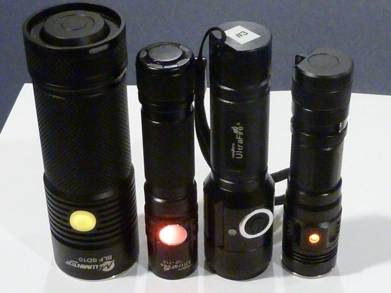
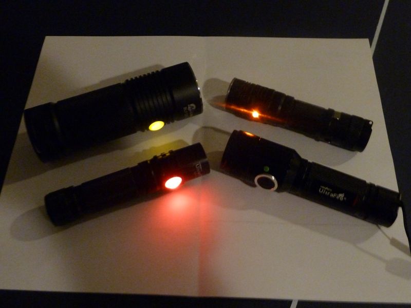
Some mods running Narsil w/Indicator LED support (BLF SD10, UF-T18, ZY-T11 clone, SWM C20C):
You can do anything the included GPLv3 license allows. Mostly, it means “pretty much anything, as long as you share the code”.
Awesome. It’s now (finally) merged into the repository.
U 2 contribute alot here, admiration ![]()
Thanks TomE ![]()
Thanks All! Notice the brightness of those LEDs? Wayy too low resistance used. On the UF-T18 there was a resistor already mounted on the switch PCB, but must be low. Probably only used for blinking in stock driver - looks ok when blinked, super bright when on steady.
Actually the UF-T18's switch LED is the ultimate low moon mode. It actually throws a pretty good amt of light ( ).
).
So Tom what’s the difference between indicator LED and locator LED?
Ok - I’m calling the physical SMD LED wired to pin #3 the “Indicator LED”, but the “locator LED” is the functionality of it being ON when the main LED is OFF. Thought this might be confusing, so no prob, ask away.
Thanks. Another thing to put on the ever growing pile of things to look at. I’ll keep it in mind when I return to temp control coding.
I took only a brief look at PID before deciding on something simpler. The atmel example code I found for it compiled to like 5500 bytes and the MCU only had 2048, so I put it aside and tried to come up with something tiny instead. However, I hear PID can be implemented in far less space than what I found…
wight linked to one that was supposed to compile in 534 bytes. I’ll start there. Space is certainly an issue, I don’t know how much I will be able to afford. My “development” firmware is getting full, but some of that stuff can be stripped out for “user” firmware.
I was just looking at Mountain Electronics and I saw that the DRJones H17F driver with lucidrv2 uses PID. And from reading about his UI, it seems fairly rich as well. That driver is using ATtiny25.
DrJones is making some money off his drivers though, so I presume he justify putting more than just free time into them.
Yeah, I’m sure he has spent loads of time on his drivers. I was only remarking that PID is definitely possible in a small(ish) space. Hoping to encourage some of these talented people working on drivers and firmware, confirming that it can be done. It wasn’t long ago that TK didn’t know it could be.