Hm, you didn’t leave me any questions to answer lol. Its funny you mention the piston board, I did a major overhaul last night, removed all the resistors and made the bottom smooth, also made the bottom pickup ring solid since there wernt any components down there to need grounded anymore.
Oh and that little aspect that I switched it to a PIC so I can run tterev3’s UI
Sweet! Odd thing is…EVERY board I have designed has the SOD-323 on em…I have no idea what brain fart made me put a SOD-123 on these two new boards…jeez
Definitely want to see the new design…and I might have to invest in a PIC programmer
All I know is that whatever size pads were used for the diode on the other Oshpark boards are almost exactly (if not smaller) than the tabs on the SOD-323 diode, and can be... rather tricky to work with sometimes. Bigger would be better, even if it doesn't follow the standards for whatever package design. I'd almost like to see a plain 0805 resistor-sized pads, the diode would still fit on that just fine, and would make things a lot easier when something other than a diode needs to be stuck in that location.
Is it possible to get this in a 14mm size? Is there enough contact around the edges to file it down to that size and still have it work?
I’m trying to find a one-sided driver to put into the CNQG brass AA light, and it’s pretty small. The stock driver has a nice boost circuit but no MCU, and I care more about custom firmware than I do about 1.2V compatibility.
possibly…shaving a mm off the driver will definitely smoosh everything together and make it that much more difficult to solder
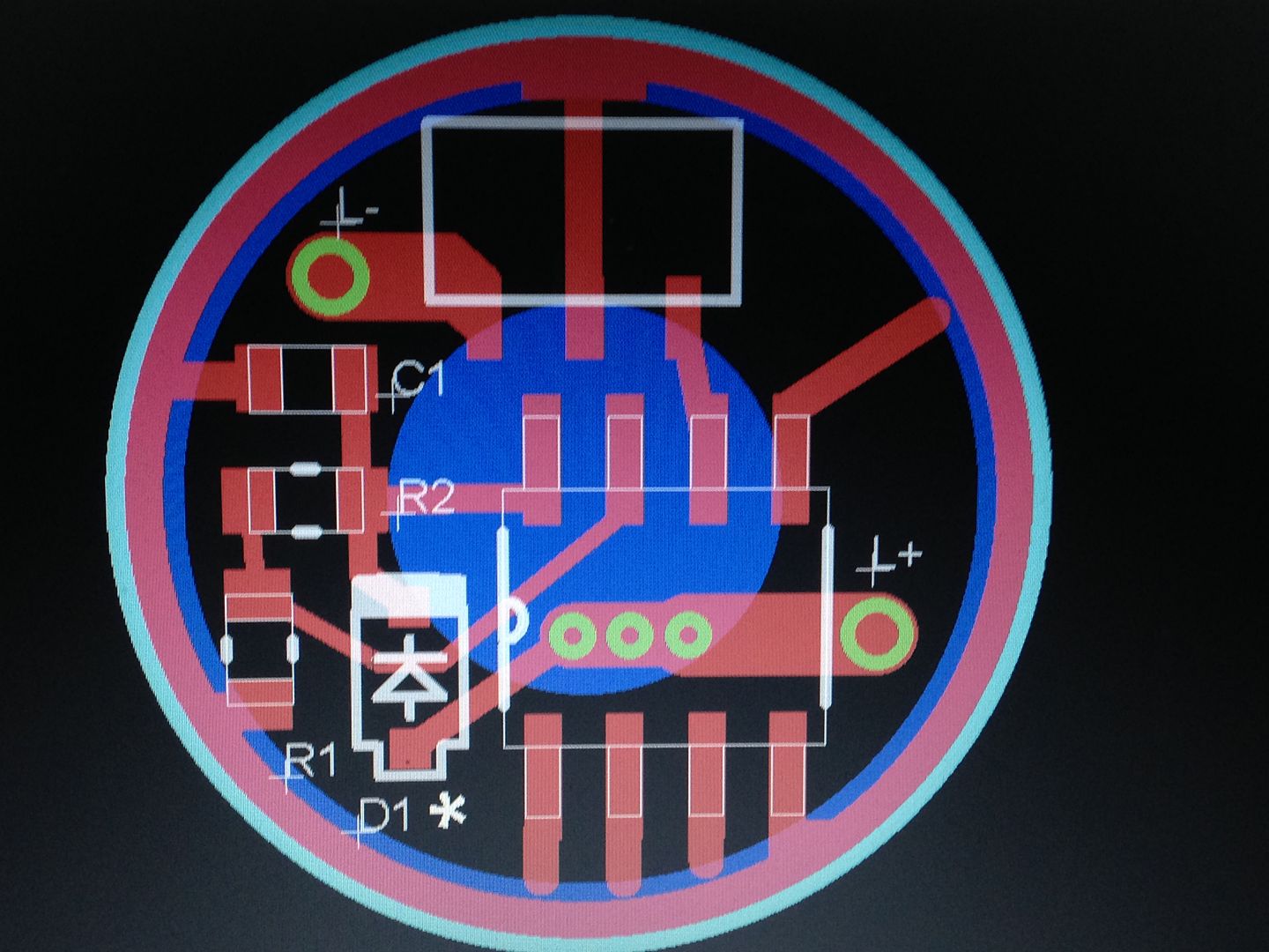
it looks doable…just have to move all the components closer in to the MCU and then resize the entire diameter down (might make re-flashing with a SOIC clip difficult or impossible)…I will give it a go ASAP…shoot me a PM to remind me please
What kind of drive current are you looking for? It might be possible to rotate the mcu counter clockwise 90 degrees with one 7135 footprint lining the up the pwm pins. Smooshed is right though.
I suppose 380mA might be okay, though I was really hoping for more. 700mA or 760mA is probably sufficient on a 1x14500 light. Not sure how much a FET would actually provide, but I doubt it’d do more than 2A or 3A, and that would be reserved only for turbo or brief bursts like strobe.
Really though, 1x7135 would probably work for most of what I do. It’d probably have a maximum output roughly on par with a L3 L10, which isn’t too shabby for such a small light.
2 stacked 7135’s is only 3.5mm so total board height would still only be ~5 mm. That’s probably similar to a board with a small coil. Playing around in eagle now to see how it looks.
It looks like this board is about 3.5mm thick, even with the coil. The PCB is particularly thin. For comparison, the BLF22DD I got from RMM looks like it’s actually 0.5mm to 1mm thicker where the FET sticks out. I don’t think the driver cavity has room for more than about 2.5mm worth of components above the PCB, and the PCB itself is only about 1mm.
I think 1x7135 is the absolute maximum which might fit. I can probably live with that though.
Ideally, yes. Unsoldering to reflash would probably hinder things significantly. I might be able to shave down the clip tips though, to make it fit easier.