Jim, that’s a yes. I wanted to test the output of the emitter at 700mA and didn’t know how to do that. But I do have some 7135 chips. So I stacked 2 chips for the 700mA output and soldered them to a bare XP-G SinkPAD for stability and some heat sinking. The light powers up pulling .72A and shows me exactly what to expect. And it’s quite bright at that! I’m literally holding the wires to the battery here, just checking output to get an idea what my custom build will be doing with a driver making 700mA.
And yeah, direct drive is not recommended by any of the LED manufactures for various reasons…one of which is the possibility of cooking the power wires inside the dome and causing the diode to go into a loop and possibly expoloding your Li-ion cell. I’d think this would only be a problem when someone (have no idea who’d do this) pushes the emitter far beyond the max limitations. It’s also about controlling forward voltage and all kinds of goodies that I can’t specifically recall at the moment but have read about. Manufacturer CYA kind of stuff.
Again, I have to thank y’all for showing me how to do this…really cool stuff!
I don’t know if you’re joking or not. This is a INPUT, OUPUT, GND, 3 pin simple as it can get device.
Look at the datasheet and how it’s supposed to be connected.
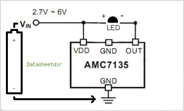
Not joking Jack, just don’t know electronics. Trying to follow the circuit (that I also provided here) I was getting a dim glow. Shorting out. It wasn’t apparent to someone with no background in electronics how to proceed.
It appeared to be simple, which is why it was frustrating when it wasn’t. The capacitors to ground were mainly what was throwing me off. Was trying to use common ground across the board which of course didn’t work.
Guess if I asked you to figure ft/lbs of energy on a 110 gr bullet at 2000 fps you’d find that easy as well? Or what shutter to use with an f/2.8 at ISO 200 on a sunny day? While I can drive a car backwards using only the side mirror at 20mph for as far as I need to go (in the dark even), many cannot…can you? All depends on your knowledge background, does it not?
At any rate, LowLumens gave me the direction and it all added up in the end for a succesful experiment…so all is well.
I took a couple of pictures (or rather, my wife did) of the output from the Nichia emitter at 1.61A vs .72A and the results were surprising. Not anywhere near the doubling one might expect. Brighter at 1600mA yes, but not all that much brighter…F/5.8 at 1/2 second ISO 100 yielded decent results for both outputs, which wouldn’t seem to be reasonable. But it is what it is! lol
Hi
I’m trying to build my own flashlight using a 1W-350mA-3V high power led, 1 amc7135 and a ion-lithium battery. When I connect the amc7135 to a 3.7 voltag regulator, it works fine. But when a connect it to the battery, the current rises to 650mA or so, do you know why does it happen? Do i need to use any extra component when using the battery?
Thank you very much for your help.
You’re basically making a single mode board without reverse polarity protection and without the board. Once you get the idea it’s pretty simple but it doesn’t seem that way at first. This is how I’ve been regulating my solitaire mods. Two chips with the ground tab soldered to the underside of the pill.
What threw me was the out leg going to the neg on the emitter and the neg from the battery going to ground on the chip. Once that was pointed out it made perfect sense, but the multiple ground points with caps on the diagram really had me confused.
Juanita, I don’t see how you could get 650 when running through a 350mA regulator. If it works for your regulated power supply then I would think it’d be the same for a cell. But I’m easy to confuse! lol
Perhaps someone else here could answer that…anyone?
Hi Dale
I feel the same, I think some how it is bypassing the IC, and I don’t know why.
I have exactly what’s in the circuit above, and it works perfectly when connected to a regulator, but when I change the supply for the rechargeable battery, the IC heats up, and doubles the current… :s any possible explanation?
Juanita, have you tried upping the voltage of your regulated current to the same 4.2V of the battery to see what you get then? As you know, a fully charged Li-ion is 4.2V fresh off the charger. I still don’t see why that would matter as long as the chip is wired correctly it should regulate your power the same.
You need Texas Pyro or LowLumens to chime in on this one, somebody that knows far more about this stuff than I do.
I kind of agree. I posted on your original thread, and, assuming you were measuring the current at the right points, and if you were seeing 650 mA, that’s like 50+% more than the max spec’ed sink current, already.
Edit: So maybe try a new chip again, and see how that behaves.
By no means am I any kind of expert here, but if you could show the driver you’re using someone might spot what’s wrong. I’m thinking you may have a shorted portion of the board that’s not allowing the default modes to operate.
From comments made to me when I was having issues getting the 2 7135 chips to limit an emitter for a trial, you might have done just that. Use a magnifying glass to check the added chips to ensure you don’t have one of the legs grounding to the middle leg with your solder. They’re so small it’s easy to do.
i found problem…the board is not the same. some seem to have different modes. the outdoor site says that *2 is the one i wanted
but it turns out it is the default. different suppliers!
added 3 7135’s not sure how much more output i am getting. wish i had tried driver with out them.