it’s constant current ,but If you use the FC40 LED on the XHP35 driver, it will flicker abnormally.
I use 22mm boost driver for the GT FC40 on Convoy S21B with XHP35.2 4000K 90CRI and It works fine. I suspect there is no 2.5amps on a tailcap.
Glad to see the new 3x21A with 25A buck driver! This is a big uptick from the linear 17.8A driver in the SFT40 version.
1 Thank
I would love a brass S2+ with the same design as the aluminium! Don’t mind the weight at all.
2 Thanks
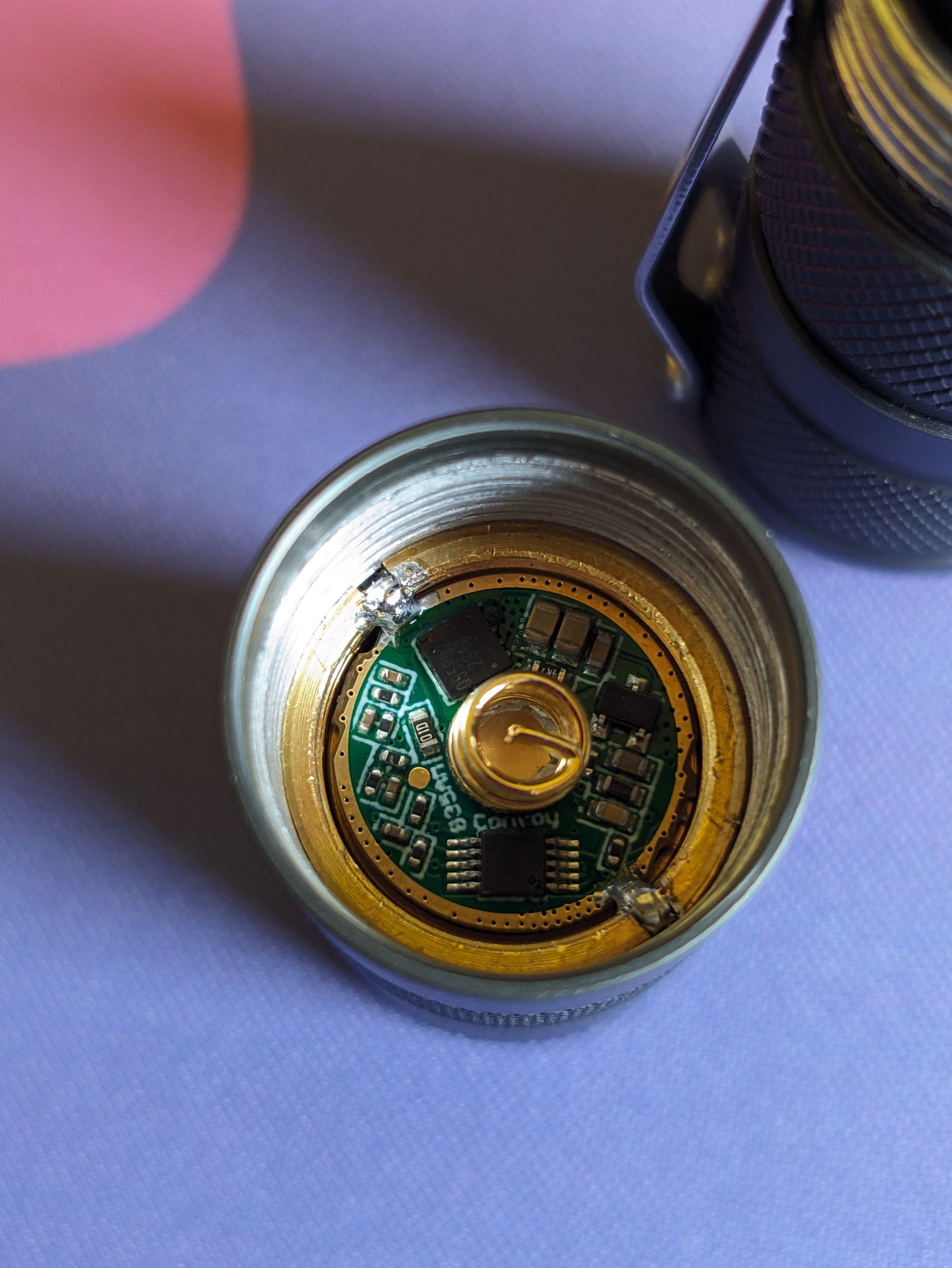
Hi! LMP LML2AW.DC Can it handle 8 amps?
See my test ![]()
2 Thanks
Hi, I just got my order (B35AM and 2A 17mm boost drivers) for my S2+, but the drivers do not fit.


The driver retaining ring has a smaller diameter than what it would need to have to fit the driver, so it collides with components on the PCB.
I thought the S2+ could take all 17mm convoy drivers? Is there any way to make it work?
EDIT: Made an ugly workaround:
You need to grind or file down the retaining ring in the S2+ and C8+ for some drivers
4 Thanks
TIL. That sounds like a lot of effort, I’ll just solder them from now on lol
There are/were pills and retaining rings sold that were thinner and had space for all drivers
2 Thanks
If the pill is properly pre-heated (without LED board and thermal paste applied to it) it looks very clean and smooth if drivers are soldered directly to the pill. To get it even more clean, flux residue can be cleaned as well.
It is important that the pill has the same temperature as the solder points.
This method is not suitable for changing drivers often, though.
2 Thanks
A dremel(rotary tool) makes quick work of it.
Soldering to the pill is a pain.
As Koef3 said, preheating the pill is the best way to get the solder to flow properly.
1 Thank
Yeah, I heated the pill to the melting point of solder before inserting the PCB and soldering it to place.
This needs at least 0.5mm shaved off along the entire diameter, on a part that’s too small and fragile to properly clamp it into a wise… Still sounds annoying to do ![]()
I am embarassed to admit my “temporary” solution has been to simply not attach the driver to the pill at all. Initially it was just to test the LED in the reflector but I seem to have allowed it to become permanent.
It would be very handy if Simon were to offer pre-ground driver retaining rings though *wink wink nudge nudge
5 Thanks
It’s really not at all. You seem to be over thinking it. Even if you don’t have experience handling a dremel. I even use a cheap made in China hand dremel that’s meant for arts and crafts and it is the easiest thing. I think I paid $8 for it shipped.
2 Thanks
It’s not that complicated, just clamp it on some small vise grips (grabbing it on the top and bottom like a coin), and stick a dremel with a sanding drum on the inner edge.
I’ve done it a few times. Just be careful not to breathe in the brass dust (a respirator is important), it’ll give you one hell of a sore throat. I use a cheap battery-powered dremel-clone, with sanding drums bought for a few bucks on Aliexpress.
2 Thanks
I did the opposite with my Jaxman Z1 as there was no other way to get a low thermal resistance joint between the MCPCB and pill. They had used some sort of thermal epoxy but that caused the stock XHP50.2 to die with the 6V8A driver. Don’t have a replacement XHP50 to test with but the SFQ43 I used seems to do just fine with that driver, might swap for an SFT-40 and the 12A FET driver though.
I think there’s something wrong with the 6V 8A driver. With P42A at 3.9V, load voltage should drop to 3.6V, but low-voltage protection is already triggered. Is anyone else having this issue? Is the 6V 5A better in this regard?
Shure, it got much lower cut off voltage, something around 2.9-2.8 volts.
I have a 6v 4a with this same problem. Asked Simon months ago and he said he would test it.