Courui "Even Bigger Head" D01 Projector: 113mm Lens , Luminus SBT-70 @ 13.5Amps *Build Stage*

MEM, I know you know this is some epic :bigsmile: lens knowledge your are imparting here :slight_smile: thanks

You have confirmed several of my thoughts & suspicions about this subject & straighten out many questions & raised many many more since you started posting, but i think you are right about most of those can only be answered by practical experimentation :slight_smile:

Using some meniscus lenses to basically making the big aspheric much thicker & work as with a much shorter focal length, and guide the light so it is not wasted is a very very good idea :slight_smile:

Am i on the right track if i say an optimized set up is something like,
LED>reflective aperture>meniscus lenses of different sizes to make each step not to large>aspheric lens

I wish i could afford to buy lots of good lenses to play with some of this, but first i have no idea what or where to get such items & i honestly don’t think i can afford it, if i even would be able work out what lenses i would need to start.

I think for now i will have to play with cheap hosts like the Uniquefire 1504 when it gets released.

But i really hope this level of discussion continuous here, because i think many here really want to push the envelope in this area, but i have read many accounts from very experienced modders like Dale’s & OldLumens for example on big aspheric builds that end in frustration.

Finally i wonder if it would be possible to use cheap lenses & maybe AR coat them at home, or maybe ask an optician to send the lenses to what ever place they get eye glasses coated for a possible cheaper option.

Mine hasn’t ended, it’s just temporarily shelved while I figure out what to do to fix it. :slight_smile:

Buck machined a large aluminum heat sink with a press fit copper core to fit in the Solarforce S1100. The height was carefully calculated to put the emitter surface at the called for distance from the big aspheric from Edmunds. It’s really beautiful work, but it doesn’t work. I’ve tried my little hand made aluminum partial hemisphere to focus light back on the emitter and with the light on a very low moon you can plainly see that the focus is pretty dang tight on that square die surface. So the difference must be between the small de-domed XP-G2 die and the very large flat base of the aspheric itself. A miniscus lens or two to bring the light into the aspheric more focused is probably exactly what it needs.

I’m reading and researching and sleeping on the lens in hopes that it will impart to me through osmosis what it needs to be awesome. :wink:

Not having any prior experience with this sort of thing, I’m looking for needles in the proverbial haystack without knowing what a needle looks like.

I know you haven’t given up & i absolutely believe you will succeed :slight_smile:

But my point is that it is a little scary for me, as still very new to this to jump in when i know you guys have tried & found it hard to grasp & get a fun build going & it is often a lot of money to get started, i hope somehow it will be possible to get some good result also on a tighter budget :wink:

One of my biggest hurdle with this kind of multiple lens stuff, is that it is all based on some fundamental math……that i up to now have failed to understand.

you and I are in this little canoe together, paddling furiously against a strong current. :slight_smile:

Don’t forget to admire the scenery guys :wink:

It’s not hard to make a fairly impressive/unique light with pretty much any large aspheric/PCX lens, (even easier when you start with a gorgeous emitter like the sbt-70) what is hard (it seems) is to make it a record breaker in terms of numbers. :stuck_out_tongue:
Certainly it seems there’s a lot of variables in both the design of the optics chain as well as the selection and quality of components. Much more to think about and get wrong when compared with your average reflector light.

MEM, from your testing do you have a rule of thumb idea of what a really well made and adjusted “reflective aperture” can gain in terms of percentage throw increases. Of course this will depend on a lot of factors but do you have a gut feeling like, “if I can boost lux by more than XX% I’m usually happy and I’ll call it a day”. I think it’s really handy to have a rough idea of where the gains can come from and how much can theoretically be gained by going that route.
Then we’ll have a benchmark and can compare attempts at making our own collars from various kitchen utensils 8)

We tend to have very good ideas of what dedoming and AR lenses can do to the average light but when it comes to collars and aspheric lights those general rules of thumb tend to be less well understood. At least that’s the impression I get.

I’ve already seen a 15% improvement with my quick cupcake collar so that’s encouraging for some bigger gains here.
That collar I used is definitely not going to be the final one btw, very rough work in sanding and drilling just to be able to get it into the light for a look. It’s already in the bin :slight_smile:

Cajampa,

The reflective aperture does not change the position of the starting plane of focus remember, which is the die, so the reflective aperture can be left out of the thought process when thinking about the bending of light rays at least. It is just a “freebie gain” in the system you might say. Now, as far as optical setups go, it is true that there are laws in physics stating that adding lenses together will not increase throw, even if there is zero loss through each lens. The problem is, these are laws to assume in a perfect environment, which often does not exist. Because no single lens yet that I have found is perfect, sometimes arrays of lenses can outperform the available single lens. That is the theory which I use, and based on simple logic can be quite obvious a theory. I say obvious, because the optical quality of some lenses are so imperfect a mate to an LED, that the image alone tells us the light can be bent more effectively into one image. This is what typically starts the arguments between some as they turn to formulas and say that addition of lenses only results in a larger image. Those theories only hold true when there is nothing left to gain. I find there is usually something left to gain. The idea of the aspheric lens itself documents this. Its curvature is not defined specifically, such as one radius in a spherical (convex) lens. Different aspheric curvatures result in different ray trace profiles when that lens is then analyzed in the real world. By adding a meniscus lens behind another lens, the net ray trace profile resulting thus varies. So it can be seen as essentially creating different aspherical curvatures through the combination of these multiple lenses. (If camera manufacturers listened to some of the “light experts” on the forums, then your cameras might end up with one lens which moves back and forward. See what your pictures look like then. :slight_smile: ) When a person cannot create their own single aspheric lens in their garage, that person’s only real option is in fact to add different lenses together. What I have just explained is the difference between a perfect world of physical law and formula, and the realistic world of the manufacturer creating the lens. In the perfect world, a perfect profile exists for one LED shape, and a perfect lens could be made for it. Notice how I keep using the word perfect to emphasize that it’s not likely going to happen. :slight_smile: Now, going right back to what you had asked, not only could you place a meniscus lens behind the aspherical lens, you could even place a larger meniscus lens in front of it, too. :slight_smile: Now you have created a new system focal length, with new diameter. If the final optic diameter grows, it can be assumed that the light gathering of that system has now also grown with it. As if this weren’t enough to think about, the starting meniscus lens will perform better in the optical system when turned in one direction, vs the other direction. It is all relative to the way an LED emits light from its square die surface. I am a believer that a round die is optically better suited to a round lens. The problem is that, the specific LED technologies vary between those who make the round dies, and those who make the square dies; I.E. Cree and Luminus. It would be nice to see Cree have a round die high-performance chip paralleling the XP-E2/XP-G2, with same Cd/mm² intensity across similar total and flat die area. The reality is, it may simply not be possible based on their manufacturing processes, or manufacturing choices (as more dies can be made from squares than circles, this trickles down to consumer costs to buy the LED if the MFGR were to choose a different die shape). Yes, that is quite a side-tracked notation to encompass from your question, but something to consider as we note how the real world products may differ from “perfect”.

DBCstm,

Let me ask you this first. When you try a domed, stock-form XP-G2 on same pad height in the others place, is the light in better focus vs the de-domed one?

The dome itself is essentially a very low quality meniscus lens (with a void filler gel), and it can be used when still attached to test for a couple mm worth of focal length. Though the effect it has for that test will be greater with a lower FL lens in front of it. One thing you can do for a higher FL lens, would be to simply take a convex-convex, or plano convex, with long positive FL, say 25mm diameter by 100mm up to 150mm FL, start it very near the LED, then move it forward in small amounts if you believe your focus to be off by only a few mm. But as soon as light can pass this small lens and hit the larger lens, the original image will start being drawn again. So you must keep all light going through this smaller lens and it will only net you maybe 10-15mm worth of test room. This would be another quick-test method, anyways. Just remember the lens you decide to implement, should allow no light restriction from the final output lens in the place you mount it.

LinusHofmann,

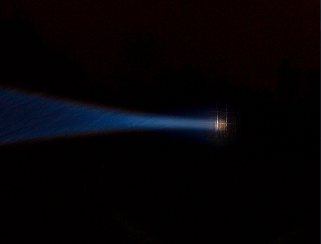
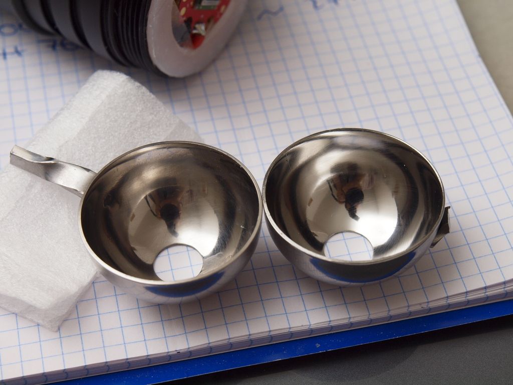
Gains can be as high as 50% using reflective apertures, possibly more, but relative to the die technology and kelvin range of the LED also. The larger the aperture, the better the image re-creation will be. But of course, it can only get so big and still remain practical to fit inside the body. But the larger, the better. I would say a practical number to aim for through general garage methods would be 25% lux increase.

I hope this sheds some light. :slight_smile:

Very “enlightening” post indeed :P, thanks! :bigsmile:
A 50% improvement would be quite something and certainly if we can get to a 25% increase that’s nothing to be sniffed at.
Especially because, as you say, the improvements gained from adding a reflective aperture are essentially “free”.

Well, unfortunately with Luminus retiring the SBT-70 and not replacing it with a similarly sized round die emitter or smaller, I suspect the options are going to remain limited to square emitters for the foreseeable future at least. :frowning:

I think maybe part of the problem with mine is a 75mm aspheric with a 30mm focal length.

Why is that a problem in your mind? Assuming the lens has a 71mm aperture diameter that works when light strikes it, 30/71=0.42 for an F#. There are 50mm lenses which will produce beams around the same size as that (at a higher F#, like ~0.6), but you’ll have almost twice the light intensity in your die image.

What Edmunds lens is it (link)? I figured you would have the 75x50FL from Edmund, which is in their Aspheric Condenser Lenses section. Or, you are using the BFL given of that very lens, in which case F#0.42 is not the actual F#. But I just realized its BFL is 30.5mm; the reason why I’m guessing it could be this one? http://www.edmundoptics.com/optics/optical-lenses/aspheric-lenses/aspheric-condenser-lenses/46244/

That line is precision ground on the plano side, and molded quite well on the aspheric side. I have the 80x59FL Edmunds lens, and I can tell you it surely focuses well. You should typically put each lens on an optical translation stage like I have, move the dials right around the focal point to find the specific lens’ FL. The reason I say this is, they are only stating a +/- 7% accuracy on their specs for the FL listed for that line. If you looked at the BFL first, saw 30.5mm, then had the pill designed for that spec, there’s a 14% range there which easily gives an idea of why you would not achieve focus playing the “FL lottery”. Good focus is more like a <2% range.

But regardless, you can definitely achieve focus with a thin coated positive-FL lens addition if you are coming up too short on the FL. What can you do right now to move your lens? Is your lens locked in place just by a bezel being tightened, glued, etc etc? A plastic spacer ring could work depending on how the lens is actually mounted.

LinusHofmann,

If you were able to center the reflective apertures properly and very well in each situation, use a type that starts with a good surface, then just machine them on a lathe like I do, for a given LED, a given lens size, combined with a given aperture hole size, one is going to play out to have the highest gain based on the host body of the light chosen that permits the largest reflective aperture to be used in conjunction with the lens, but yet another variable then arises. F# of the lens. Since you are only requiring that the lens be covered with light, the reflective aperture only needs a hole as big as the angle of light escape needed for coverage. If you were to always assume that, and not hold each as a restriction for choosing the light body, the next amplifying phase variable would be the LED phosphor substrate type and color bin. Those would determine the gains witnessed by the same aperture size. These are much less predictable in configuration since you are reflecting all light colors back onto the phosphor. Some phosphors will respond differently, for example a phosphor with higher starting kelvin should re-illuminate to the highest brightness levels vs say a tungsten “High-CRI” bin. This is because of the mechanics occurring at macro levels, the physics of the photon particles themselves and quantified energy states of colors. Some colors within the white light will cause increased excitation of the top phosphor layers. This is why the kelvin temperature change occurs when used with these. Different light frequencies excite different colors in the phosphor matrix from the front traveling back, instead of from the back or bottom of the die traveling forward. Colors with higher energy levels will excite more photons out from the matrix that require lower energy levels to achieve excitation (blue>red for required stimulus energy). So on the second pass, when the light is recycled back, you may get more reds and greens achieving excitation before the deeper layers can be reached by the remaining light. If reds and greens are excited further on the second pass, and blue is only met with a small percentage of returning blue light waves, the whole color blend takes on a new value, and a new color bin occurs on the 1931 CIE curve. When the LED’s dome is still on, light gets trapped and scattered at the die-to-dome-medium interface, which boosts green area output, giving the phosphor a tint which is weighted back towards blue-green. When the dome is removed, more light immediately leaves of all colors, and less re-excitation occurs, making the tint shift appear lower in kelvin, but only because of original light wavelength ratios produced. You aren’t really lowering kelvin in a de-dome like many think, you’re revealing the die’s natural working kelvin. Since less re-excitation occurs when de-domed, less lumens are produced after the de-dome, but not enough to account for the apparent expanded die size change—making the light total still more dense in energy. Domes themselves are a method of re-excitation used by manufacturers to gain lumens, while at the same time giving an optical shaping characteristic to the LED’s output.

I appreciate that a lathe would be ideal in making these things, unfortunately they’re in short supply around here. :stuck_out_tongue:
That’s why it would be great to see what can be achieved without one, I don’t really see much that can’t be achieved with a bit more time and careful grinding/mounting of the collar.

What do you use as a source item to make those stainless steel apertures you showed in the photos? They do indeed look very good in terms of geometry, maybe a bit big for most lights though? The limit inside the courui host is around 4cm across, and the cupcake molds just about max that out.

Cheers
Linus

That’s the one, and yes, the BFL is how it was set up. The lens fits in the bezel of the lights head which has a stainless retaining ring that holds the glass in place. The large head then screws onto the pill that holds the die. When this light was modified, the Cu/Al heat sink was built as a pedestal to bring the die to the 30.5mm back focal length. The head can be unscrewed to pull the glass away from the die, but it’s not all that stable when this is done. The glass lens itself really has no room in the bezel to be moved around.

I could remove stock from the top of the pedestal, then to achieve optimum focus it could be shimmed if/as necessary?

Perhaps my 5M range is too short and I’m not achieving the best results, I’ll look at that too. I did affix a second copper star under the first, raising the die closer to the lens, with mixed results. It lets me adjust focus to the other side of that measurement where the pedestal was set, but I’ll need to double check different distances to see how it’s affecting at long range.

Still though, it’s ironic that the factory reflector put back in the light allows a doubling of the Kcd figure and easily shows a Cedar tree in the night at a little over 500 yards away.

I have a pad of aluminum that I made a quick release dovetail on for attaching in my camera tripod quick release plate, I could hot glue or silicone the lens onto this pad and then mount it in my focus slide rail to allow precise movement front to back for fine tuning. Would this work to figure out the right focal length for this specific lens? At what distance? Going for a maximum throw, how do I figure out what I should be seeing at closer ranges for build purposes? Not exactly easy to take lux readings at 1760 yards or more.

I’d put that down to what’s causing the main issues here. Designing an aspheric/lens light without any ability to fine tune the back focal length/focus is a big mistake imo.

Even if you machine everything precisely and have a lens with a very tight tolerance I’d always try to have some part of the optical system on threads so you can easilly tune things even after everything is assembled. Doesn’t matter if you make the lens mounting adjustable or if you move the pill but some threads to allow smooth and fine adjustements are really crucial.

With my courui I have no shortage of places to adjust focus. The most useful in terms of quickly testing focal length changes is probably being able to unscrew the entire head some way. It’s not secure enough to leave it that way but to quickly get a feel for what kind of adjustment needs to be made it’s very handy.

Then there’s a pill that’s mounted with a threaded section to make that tested adjustment more permanent. It’s nice because it means I don’t have to worry all that much about where I secure the lens, as long as it’s within a couple mm of the ideal focal range the rest can be tweaked simply by screwing the pill in or out some.

I didn’t make this one, just trying to make it work! :slight_smile:

Thanks again MEM :slight_smile: i got what you are saying, don’t get hung up on not knowing the math behind, because the math only describes the perfect version, and in the real world & an extra complicated real world with various led shapes and different lenses of various quality the math isn’t applicable because it can’t deal with all the real world imperfections.

About a round & bright Cree led, something i have been meaning to test, is how an xp-l or xm-l2 dedomed but with blacked out corners would look :slight_smile: to get a round shape out of them.

The discussion about dedomed leds & what phosphors are most excitable was very interesting, so we should always start with as high kelvin before dedoming as possible, to get as much blue left in the light to be able to re cycle as much light as possible by re-excite the phosphors.
And the tint gets warmer by both the dedoming & light recycling anyway.

Today i tested an 12,5mm aspheric on an dedomed XP-L V6 3A in my DD Zeusray that has an 28mm aspheric lens stock.

And it worked crazy good :open_mouth: I fixed the 12,5mm lens on the 18awg soldered wires on the sinkpad, so it was only some mm from the dedomed led, i haven’t measured exactly but the visual of the soldered 18awg + the height of the dedomed xp-l should be enough to get the picture :wink:

And the light spot got colder, it got to a much more pleasant NW i say almost back to 3A in the spot or maybe even 3D, and it got MUCH larger & in perfect focus :slight_smile: and it felt brighter.

I did check the throw outside just now and it throws quite a bit further and with a MUCH bigger & brighter spot, i am so surprised it worked this good.
The only problem is now i can’t use the widest flood on the zoomie.

I was surprised it got colder, i guess that mean i got some light recycling similar to what the dome does, i wonder i you can use small good quality lenses similar to this tune the led better than the gel dome.
What happen if one would put a small lens instead of the dome in a reflector light? The stock cree led’s already have a gel lens and that works what if we could improve it.

Why does a gel dome make the light colder & an reflective aperture the light warmer when both are recycling the light?

Well, the weather may be crap but this light still put smile on my face.

Went out ion the drizzle to test out a possible new beamshot spot, a raised hill with good forest border targets 180m in one direction and 450m in the other. It’s a pretty great spot, so I’ll be doing further beamshots with my other lights up there soon.

I had some fun spotting targets at different ranges with this beamer, not much in the way of good photos though because conditions were pretty nasty.
I think I have the focus dialed in pretty well for longer ranges now.The well defined circular hotspot is showing up really clearly up to about 450 meters. As a result it is now quite out of focus at my 12 meter indoor test range.

This shot is without a collar so you’ll still see the considerable (but gorgeously high CRI :stuck_out_tongue: ) spill ring in the foreground. The tree target in this shot is a forest edge at 180meters.
As you can see the central beam is very tight, definitely a true narrow beam searchlight. Not particularly practical but certainly awesome to behold and very amusing to wave around in the rain :slight_smile:

Current throw figures (measured at 70meters) put the light at 215kcd, not too shabby but I’m hoping to boost that quite a bit with a diy collar.

Hoping for some foggy nights! :bigsmile:
Cheers

My ebay melon baller arrived today and I had a quick play with it.

First impressions are very good, the inside is slightly less polished than the outside but the surface is pretty ok overall. There are some faint scratches over the whole thing but nothing that won’t polish out. The cupcakes are geometrically better but these certainly aren’t bad in that department. They produce a clean reflected image to my eyes with not too much scattering.

The great thing about these is that they don’t really require any major work to implement.
Without doing anything but cutting the handle off and installing it haphazardly in the light I measured about the same 15% gain in lux that I saw with the hand polished aluminium cupcake collar.

If anyone was waiting to see if these would work as a plug and play solution then that’s good news. Especially for those that don’t want to mess about with polishing or anything like that. They do a very good job in stock form. A >15% bump in throw for $4 (you get two usable cups for the $8) is pretty great.

The only thing you’d have to do is adjust the opening at the top of each collar to suit your particular light. For use in my light the hole in the top of the each scoop is exactly the right size but for most other setups it will require opening up some. It’s the right size and the lip isn’t particularly thick but I will still be lapping/sanding it down to reduce the lip down to catch as little light as possible.

Next I’ll try to improve the polish on the inside and see if there are any further gains to be had.

EDIT:

Bit of polish and slightly better mounting/focus (though still not perfect) I’m now seeing gains of 24% … WOW, not too shabby!
That’s comparing two readings, 2740lux without collar and 3400lux with at 10m.

Thanks for the nice news :slight_smile:

Very interesting, do you think this melon baller will be possible to use with the UF-1405/1504? Thats the light i would want to try this on next.

I hadn’t noticed that these already had a hole in it :slight_smile: very nice.
As an drop in for potentially 15% extra where these 31.75mm reflective apertures will fit, for $4 this is really good.

EDIT and now 24% that is truly a WOW :smiley:

Is the pic before or after the polish?

Picture is before the polish, I don’t have one showing the polished one yet but it’s a bit shinier overall. Most of the hazing is gone but some of the deeper lines/scratches are still apparent.
More can be done there anyway, depends on how patient you are :slight_smile:

Forgot to mention the actual size of this collar (the 1.25” version) is 35.5mm wide by 20mm deep.

I’m curious to try it with the 1504 as well, though the hole will probably need to be opened up some to account for the different lens diameter and shorter focal length. Also I doubt you’d still be able to get much of a flood mode with the collar in place. We’ll have to see. Oh and the recessed retainer for the mcpcb doesn’t look particularly well suited to getting a collar in place, but again I haven’t seen on in person yet so I’m sure it won’t be too hard to make it work.


Quickly polished version on the right

Oh and watch out when mounting this type of collar. It will get seriously hot when the light is on! So don’t use double sided sticky tape like I’m doing! :stuck_out_tongue:
Obvious even with the polish there’s still loads of photons dying a painful, ping-ponging death in there! :wink:

I know we won’t get much flood with the collars in place but, if i want flood i use a triple XP-L X6 thats much brighter and much smaller & lighter :wink:

For me these aspherics lights are purely for throw.

EDIT nice you see it is much less hazy on the polished one.

I like very much your design, well thought, clean and elegant. not much time lately to be active in BLF lately but find some time to say one or two things.

Luminus SBT-70 is something unique and can give you decent throw @ factory settings, so choosing one to build a thrower is quite an OK decision in my book if one want to play safe and not overdrive.
but, (as always, is a but around that change things :stuck_out_tongue: ) if you want to go extreme in numbers(as was my impression, pardon me me if I am wrong ) u have to take in consideration over driving a led.
lets see numbers when led are driven @ factory values:
SBT-70 @ 10.5 A output 2000 lumen and considering it have 7mm^2 surface, it produce an luminance of ~ 285lumen/mm^2 which is not bad

in the other side if u take in consideration xp g2 s2 or even s3 led from Cree:
s2 @ 1.5A output ~ 500 lumen and assuming it have 1.92 mm^2 surface, it produce a luminance of 260lumen/mm^2 which is slightly less compared with SBT-70 and that is why I support choosing SBT when playing safe.
however XP g2 can be easy over driven by a lot, and this change the result.
lets say we put an xpg2 @ 5 or 6 A than we have ~ 1000 lumen and that translate in ~ 520lumen/mm^2 which is an very high luminance and so it throw further.

we can easy overdrive xpg2 to the limit and even if it burn its relatively a cheep led to be replaced, especially compared with an SBT-70.
so i strongly suggest change emitter if you want more throw. i really like all other effort, and the work on collar. I myself have looked at ice cream tools as use for collars, but in the end i change route in my project. however i was getting approximately ~20% gain in throw, and i can confirm that.

keep up the good work and this wonderful project :slight_smile:

@MEM hm… i thought the collar recycle light so blue light have an second chance to excite atoms of phosphor, but dome in other side is the opposite effect, it lets more light escape from the phosphor die. its not acting as an reflective surface but its quite the opposite, having a lower refractive index than phosphor but higher than air it act as an medium than make it more easy for light to escape phosphor substrate helped also by spherical shape. more blue light escape than. this blue make the output more white :wink: