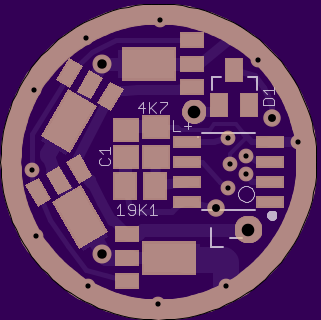
Lookie what the cat dragged in… 20mm 8xAMC driver (you could stack more chips). Nanjg compatible… uses the TINY13A cpu. Mode stars are (some of) those feedthrough holes under the CPU chip. They are labeled on the back silkscreen.

Lookie what the cat dragged in… 20mm 8xAMC driver (you could stack more chips). Nanjg compatible… uses the TINY13A cpu. Mode stars are (some of) those feedthrough holes under the CPU chip. They are labeled on the back silkscreen.
But, but... it works with the straight jumper! Nothing's popped yet, I've run through something like 3 or 4 full cycles with these (admittedly weak) cells and the light output shows no signs of weirdness. Tailcap readings show more current than it should be doing with only four "380mA" chips, though, so either the driver is eating the extra, or the high voltage on the Vdd is causing them to pass more than the rated 380mA. I have not yet been unlazy enough to unsolder the emitter wires and compare input current to output current, maybe I should do that, huh? (edit: maybe cause I'm basing measurements on typical ~3v LED numbers, and not accounting for the fact it's now driving a 6v LED?)
My few bench experiments with slave 105Cs being controlled by the SRK's stock MCU have shown that will-not-shut-off-completely-just-by-removing-Vdd-signal behavior.
Nice job Pryo. I like it.
PPtk
I see a via at 9:00. Does that connect to the pwm output pin from the other side of the board? Would it be possible to swap the 7135 at 12:00 for a 7805 (or LD2981)by cutting input and output traces (other than gnd) to that chip and jumpering input power for the mcu through that chip location?
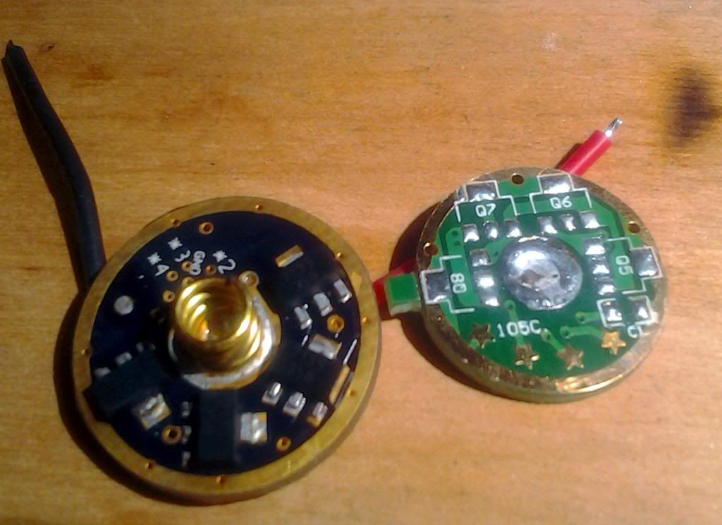
Edit I also like the layout. Much easier to make an 8 chip board doing two chips at each location before moving to the next.
The via at 9:00 goes to the PWM (Vdd) pin on the AMC7135s. What is not visible are the other four 7135’s on the back of the board.
I don’t know what you want to do with a 78L05 chip so I can’t say…
A number of people wonder about using nanjg type boards to drive the 6v mtg2 led. 5 nimhs in series or maybe two lower voltage lithium phosphate cells could do it if a 78L05 is used to regulate the input voltage for the mcu. On the 101AK-01 board I chose the 7135 chip location closest to the input diode to put the VR chip, cut the pwm and output traces to that chip, used the diode to jumper from input+ to the VR chip, and jumpered from its output pin to mcu+. The input and output caps I placed directly onto the pins of the chip using the pins as pads for the caps. I asked about the pwm trace to make sure cutting it and the output trace to the 12:00 chip location would not affect the other 7135’s.
Yes, that chip position can be used…
Another possibility might be using a regulator that is not damaged by reverse polarity (some have protection intrinsic to the design) and use that in place of D1.
Another good option might be to replace the diode with a 200-300 ohm or so resistor and add a 5V zener diode to ground. It will serve as both a regulator (when the batteries are connected properly) and as reverse voltage protection when the batteries are in wrong.
Got 3 inbound! Thanks Pyro!
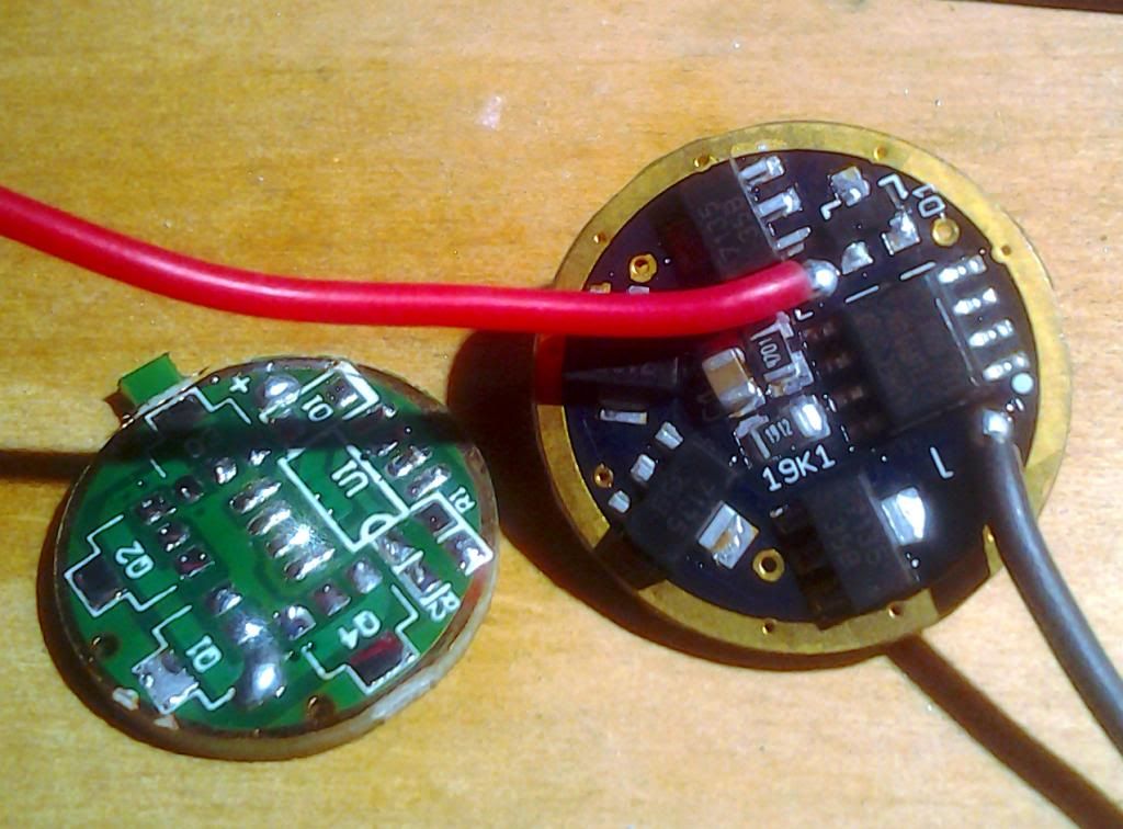
Sweet. The components that need heat sinking are on the bottom board and the others float on the upper PCB.
I can second Comfychair's experience connecting Vdd directly to 2S without issue. Done it a few times with MT-G2's. I did have the chips well heat sinked to copper (no PCB) each time.
WarHawk wrote:
Got 3 inbound! Thanks Pyro!
The boards in the OP? Guessing you mean one in Post 20.
Eventually, when I got around to measuring the output with full 2S voltage on the Vdd pins, I found the chips were not happy and output current would fall like a rock. That stopped happening when the Vdd voltage was dropped (zener regulator).
Hmmm, I guess my 7135's were probably not getting full 2S voltage. In each case, I was using loads of 7135's with no MCU. I just had the 7135's in the circuit eat up excess voltage. So I would have probably had considerable voltage sag. This was before I learned you could just DD MT-G2's with 2s cells.
One thing I have been reminding our own little group of mad scientists is that the +/- pads on the mcpcb are on opposite sides of the board. This isn’t much of an issue most of the time but when it is, it is and keeps wire lengths even.
Hey Pyro, can we get a version of your custom 20mm that uses the exact same components from a stripped Nanjg 105C, that diode you have on there, I had to wait a very long time to get
I am going to go ahead and give your build a whirl tonight, finally got everything in, I just don’t like having to strip a 105C to build a custom (I would to produce a solid 20mm however)…I do have 10 sets of ATtiny13A and control components inbound for the other OSHPark releases
In fact ![]()
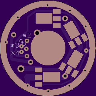
TOP:
BOTTOM:
Yup…the rework station…wow…just wow!