The way I’m dealing with them anyhow. I’ve been wanting to do this for sometime now but have been to busy. ![]()
The latest one I bought was a 4X because I have a few of them and I really like them. I also have some 3X’s. Today I’m going to address two of the most common complaints about the Skyrays they are selling these days. First I will address the poor cooling and second the poor light output. I will discuss what seem to me the fastest and cheapest way to deal with these two issues. In an attempt to alleviate somewhat these main two problems with them. These methods are effective but certainly not the best.
Cooling:
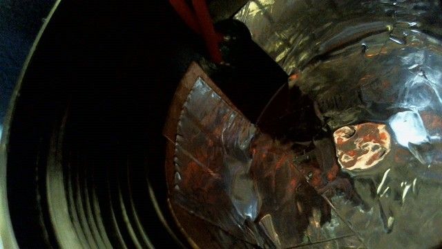
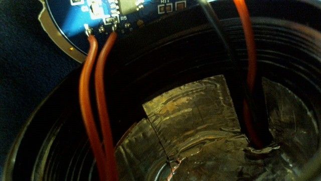
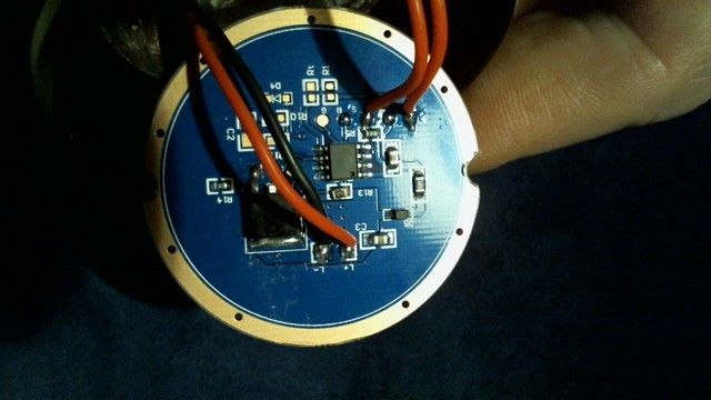
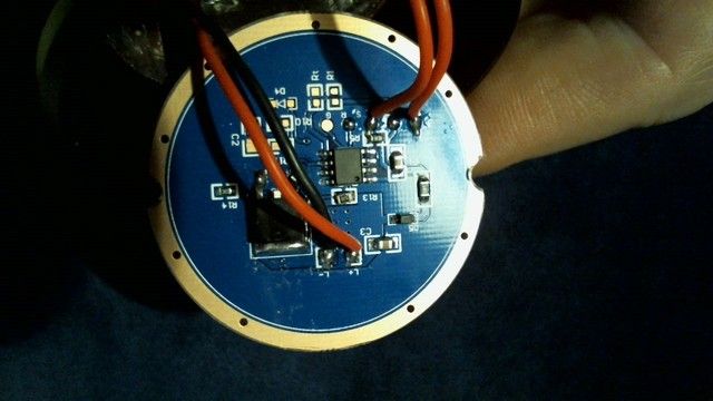
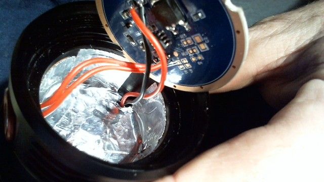
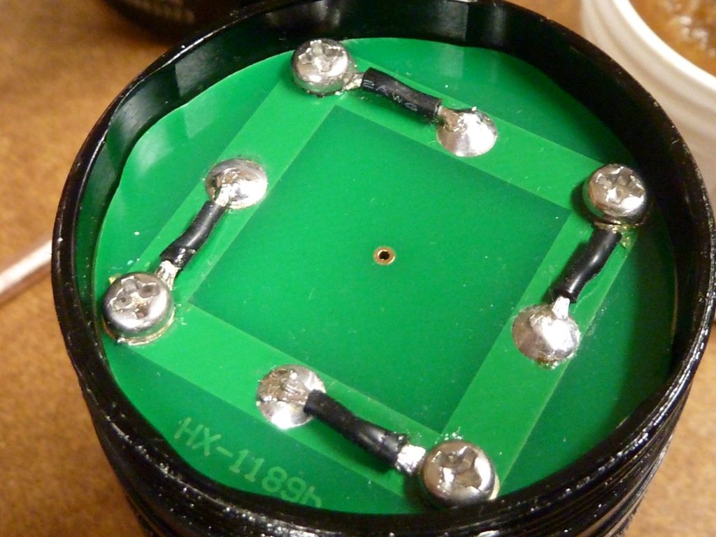
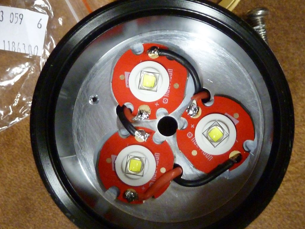
Some have shelves for the MCPCB some do not. Seems like these days most of them do not. This one we are talking about today does not have a shelf. These units MCPCB’s with no shelf have little to no contact with the main body. This is bad. Eventually they will sometimes overheat and burn out due to the lack of some cooling for the MCPCB. What I have done as you will see in the pictures is to put some aluminum tape across the bottom of the bare MCPCB and up the side of the main body. This modification worked much better than I thought it would. This is evidenced by watching the temperature climb immediately on the exterior of the head. Several times more than without the several layers of aluminum tape. That is my quick and dirty fix for the cooling issue. Are there better ways? Better tape? Copper tape? Yes, of course. This is just the way I do it fast and cheap.
Light output:
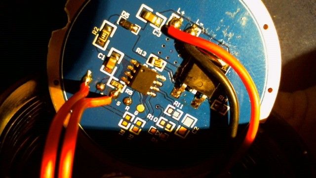
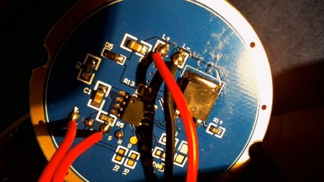
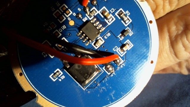
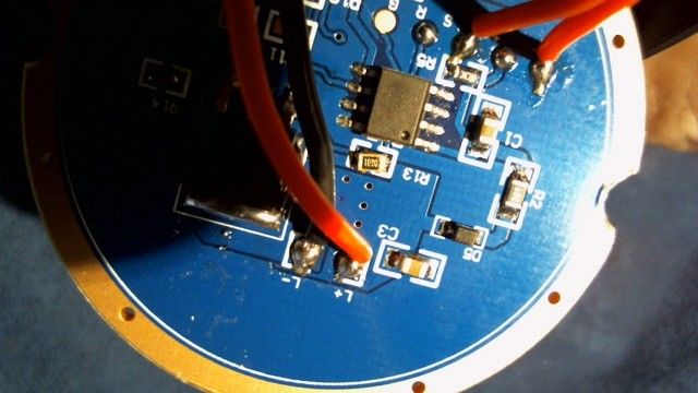
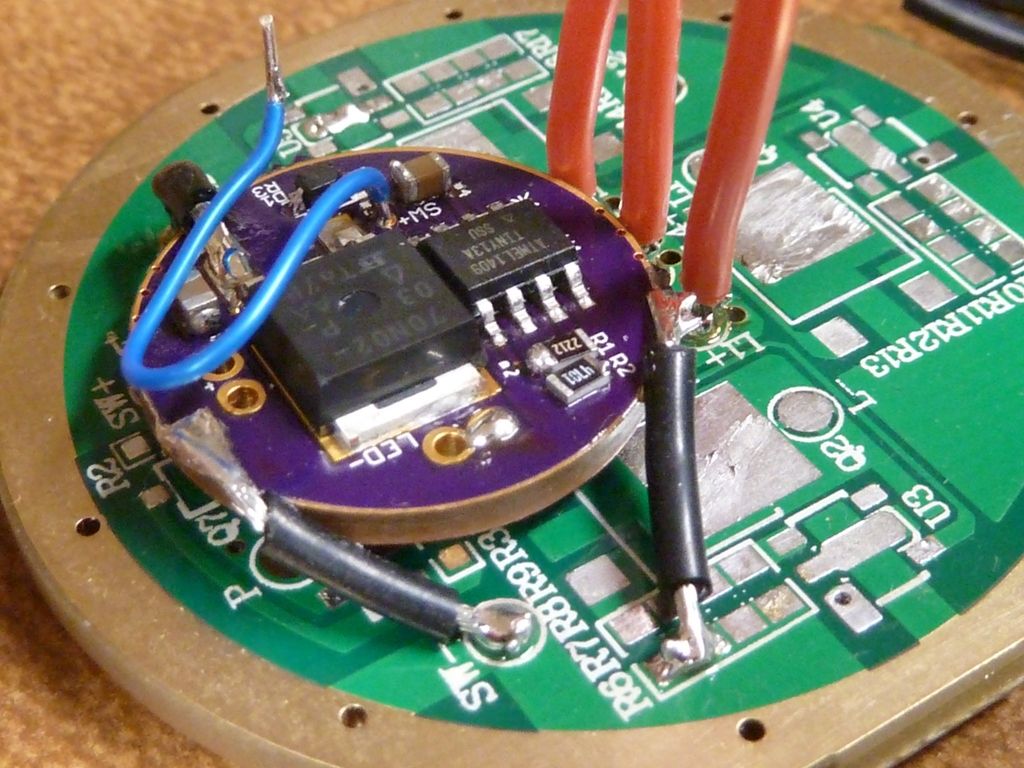
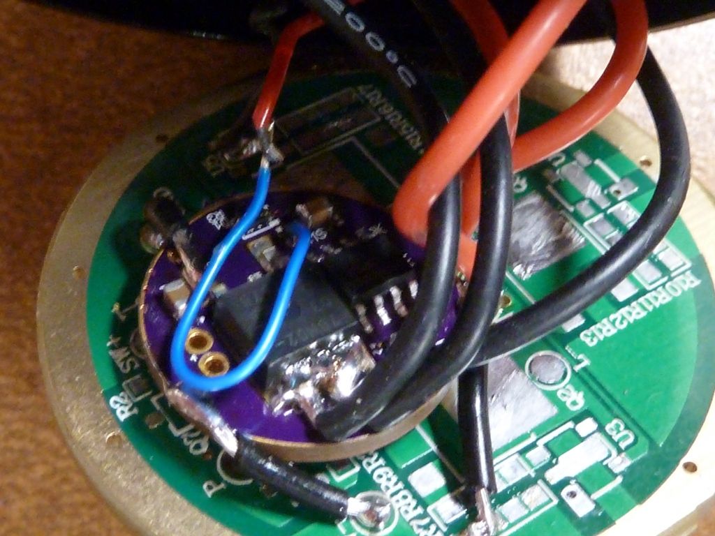
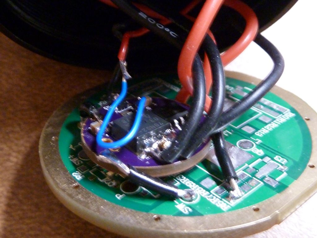
So as we know, most of them no longer come with sense resistors so they limit the PWM that goes to the FET with a 10 ohm resistor. Thank God at least for that. Before doing my mod I was getting roughly 2 amps at the tail with one Sanyo 18650FM laptop pull. My probes are 12 gauge monster cable. From the MCU there is a R13 resistor that says 100 on it. This means 10 ohms, or reads ten ohms on my DMM. It leaves the R13 resistor and travels right to the FET. So, the PWM output from the MCU goes to the R13 10 ohm resistor which then goes right to the FET. This PWM signal controls the light output. I put another 10 resistor on top of the 10 ohm resistor that was already there at R13. This now only limits that PWM signal by 5 ohms now instead of 10 ohms. When I measured the amperage at the tail it now measures 2.8 amps. There is now more available light at the output. Definitely brighter. I may decide to lessen the 5 ohms even more which may increase the light output even more. So, how did I do? Did I do something wrong?
Oh, I forgot to add that this 4X has a much less deep reflector area than my other examples. That suprised me.
Here are the pictures…
Looks like your onto a very simple mod that more than a few others will be able to use here. Thanks for sharing.
Yea! That would be great if people could get a little more enjoyment out of these severely butchered stock flashlights. I wish I could have had a chance to own one of the units that had better circuitry and three toroids inside.
I gave up on the SRK because no one had a "real " one for less than the Supfire M6.
Where did you find a “real” one?
Ehem…I have 2 original with 3 torroids for sale.or trade :bigsmile:
black or gold? 3 or 4 emitter?
Wasn't International Outdoor Store selling "real" ones at one point last year ? Or at least trying to.
I bought an x4 SRK from ebay. In a word terrible but what do you expect for $11.50. It started to flicker almost immediately and the just gradually faded so much you could look at the LED's. I took it apart and it looks like the same one the OP is tweaking.

Nice quick, low cost mod for the masses.
That resister in Bay R14 could be costing you current too if it has too little resistance. It's a pull down resistor designed to drain off residual PWM voltage between pulses. If the resistance is too low, too much of your PWM voltage may be going to Ground via that resistor. I can't make out the resistor's marking in the picture.
r14=10k
Should I just remove it?
What these SRK’s could also really also benefit from is a DTP mod. Much harder to do with an M6.
Harder with an M6? There's no SRK style light easier to mod than an M6 -- decent shelf, retaining ring on the driver, reflector with cutout paths for wires, etc...
U3 2A's on 20mm Noctigons, lumens: 5,134 @start, 4957 @30 secs on Samsung 25R button tops.
Where is the room for wires on the bottom of the reflector. I read that you have to mill out space for the wires(not easy). Nice mod btw. Which driver is that?
Don’t get me wrong, the M6 is better in every way. Its just the reflector has to be dealt with to get the XML’s on the Noctigons to sit high enough in the reflector. Not easy.
^ Yeah, that has been the biggest reason I haven't modded my M6 yet. Just haven't been in the mood to mod the reflector.
I've typically seen 30K pull-down resistors for PWM. Not sure what going from 10K to 30K would do for you though.
You could try pulling the resister. I don't believe it will physically hurt the driver. It might affect mode changes.
Here's the stock M6 reflector against the modified Shocker reflector:
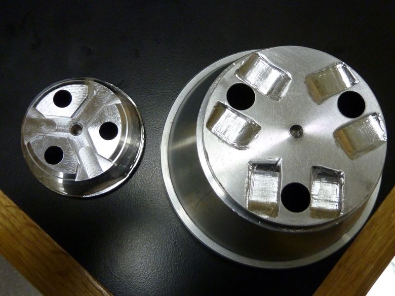
The grooves are machined out stock. If you align the LED's correctly, you still might need to trim a little, but not much - still easier then the totally flat ones like a Shocker. Can't recall and don't have pics of that from the M6 unfortunately. I think ouchy went a bit overboard on his, or didn't align the MCPCB's to the best positions. RMM has done a ton of these, and don't think he would have been doing machining on them. Best I recall I did do some dremel trimming, but not much, no risk, unlike the Shocker...
Ohh - the driver I used is a 20mm, probably C_K's, wight's or the original BLF DD 1.0. Can tell by the 2 thru-holes for Batt -. Not sure right now, but think C_K's. I've used them all.
Wow, talking about cutting it close…
The stock driver in the M6 isn’t half bad. I think their even better than anything the Skyray or clones ever made.
The only thing I want to do to my M6 is get those Noctigons in there. I have a grinder…. it would probably turn out looking worse than ouchies.
On the SRK’s though there is no mod needed on the reflector for Noc’s.
Ok - it's definitely a C_K 20mm DD driver. I used 20 AWG wires. Just took these:
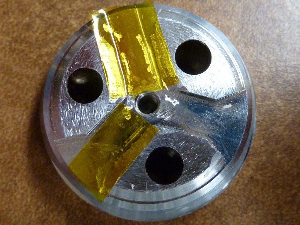
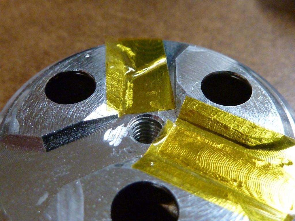
There's definitely some dremel work there, covered by the kapton tape, but it's not much that had to be trimmed. Also I have a UCLp lens - added a nice boost.
The best stock driver is shown above (stripped)  .
.
That looks good, great even. I might give it a go with mine.