Traditionally the second number on chips is a date or batch code. Used to be year and week of year. These days it is often a batch code or no number at all.
Last 7135s I bought were from Aliex, following reports of inconsistent product from FastTech. First set from Aliex came 40 of the ‘claw’ type and 60 with no logo, in spite of the listing photo that showed the ‘claw’ logo.
Second set came 200 all of good type. Dealer ‘STIME’. I did confirm in advance with the dealer that the product was exactly as per the listing photo. STIME’s current listing photos do not show the claw.
Difficult to beat the 7135 for size, convenience, performance, cost. Would be nice to have a mainstream alternative.
Apart from the inherent slow PWM response, I have had no issues with 7135s. I only use the claw type, and only on 1S drivers though. For Tom I did set up something on a test-bench, 2S 30Q, 2S2P 3V emitters, FET+1 driver. It worked and scoped fine, albeit with 10+ V inductive spikes at the FET drain and even higher at the power feed to the driver. C3 and C4 did bring those back to values comparable with 1S setups. This was a zener-modded driver, the LDO adds another variable to the mix. Zener-mod is no good for e-switch setups (high parasitic drain) but by nature it would clamp spikes. Would have to try an LDO setup.
DEL - not much time last night, but I re-visited the MT03, still with the blown 7135 and Hyperion FET - I noticed there was a clicking sound, very noticeable on strobes. Sounds like the FET goin ON/OFF, maybe just OFF, not sure. Distinct sound though - never heard that before, accept maybe in buck/boost drivers of old - not sure.
Sorry been posting this around. But, I'm having just a little fun before researching the 7135 issue. I was getting 15K lumens or so max - pretty disappointing. so I bypassed the 4 springs in the MT03 with just 22 AWG wires. Now 4 VTC6's at 4.12V do 27K lumens! Never expected to get the peak of 9K per LED, but I guess the 4 cells, specially the VTC6's help, compared to 2 LK's in a Comvoy L6.
I still have the stock double spring on the driver, no bypass, and the little longer 20 AWG LED wires (stock were shorter 20 AWG).
Edit/Update:
I swapped the 7135, added a little heat sink even to the grnd pin, made a special verson of Narsil where modes and ramping don't overlap the 7135 and FET. Tried ramping first, and it seem to blow the 7135 immediately getting into the FET range. Maybe 16 msecs between max 7135 and a low FET value was too much in too little time?
Think I should go back to the SIR404DP and give up on the Hyperion for now... What do you think?
Ohh - major :FACEPALM: , was thinking I "only" got ~15K lumens before the spring bypass's, well, forgot I left GT buck driver test code that shortened the ramping by about 25-30% or so, and even dbl click was turbo limited. :FACEPALM: :FACEPALM:
Now, stupid me, now I have way too much amps with the bypass's on true turbo.
Had a look at the datasheet for that FET. It is really impressive. Not just super low Rds, but fast too. A slower FET might calm things, but you could also just up Rgate to 100 ohms or so for a similar effect.
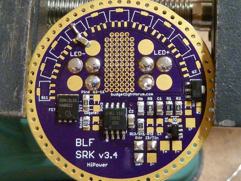
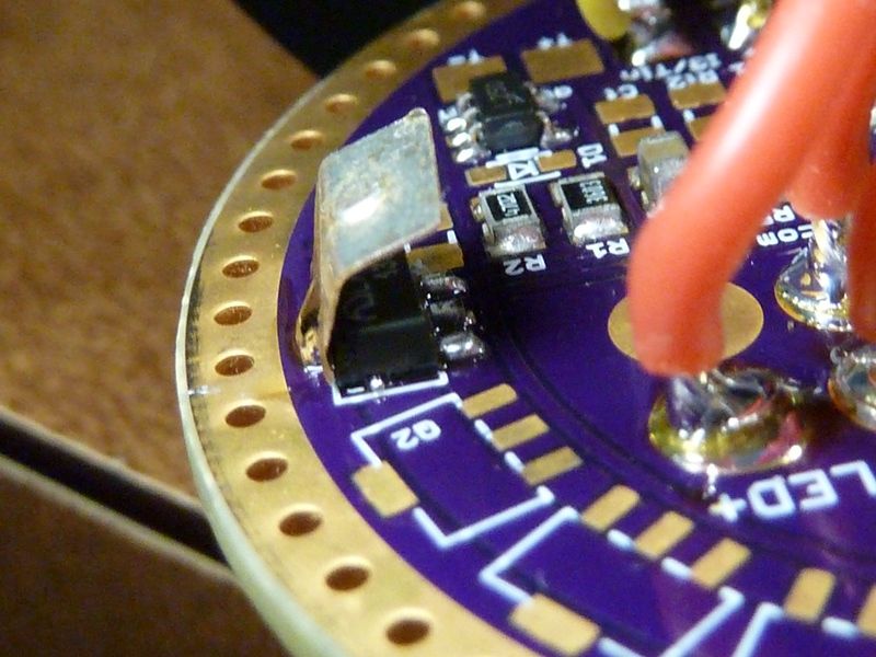
Do you have photos of the driver and the general setup? Might also be worth it to double check all the capacitor values, most should measure in-circuit. Will give the PCB layout another look over as well. It is this one, right?:
Have stuff to do around the house before the season clocks out, but will try to run some tests this weekend. Will be difficult to beat you for amps and power though .
Yes, that's it, but too late for now. Just replaced the FET with a SIR404DP, swapped the 7135 again, just in the middle of setting up NarsilM. Will default to modes first now, but still have the non-overlapping PWM's on the FET and 7135.
so 7 modes total. First 3 modes worked great, couple of times cycling. First time bumped up to mode #4 (24 on the FET), noticed a flicker, went to OFF -- light still ON. First 3 modes are all that same level, but the 4 FET modes work perfect.
Same symptoms, same problem, with the Hyperion or SIR404DP .
Hhmmm. Don't think measuring caps on the board ever worked for me... I'll try to check again. Least I can check is for continuity. Any tips? Any better way to do it on the board?
Sorry, I have limited evening times. My office/lab is downstairs, and the ladies settle downstairs at 10 PM (my mother-n-law and her sister). I'm lucky to get in 2 hours or so in the evenings. Morning are so - usually leave 7 AM for work, and the ladies don't come up til about 9 AM - otherwise I could go in late to work couple hours, pick up some more time, but doesn't work out. This weekend is my grand-daughter's baptism too .
In another 1 1/2 weeks they go back home, so I'll have longer hours.
I guess we can call that progress :). Your results are still consistent with the FET PWM doing the damage, not heat, not the 2S voltage.
C3(at Rb) has a funny color. X7R/5R caps usually have a darker dielectric. Rb is also not a good location for C3. It has to work through vias at one end and a thin ground trace at the other. It would also mess around with the ground network around the LDO and MCU. We are probably talking 10+ A spikes. It should go from an L+ pad directly to the ground ring. I would put it across Q4’s thermal pad and the top L+ pad.
Nothing else sticks out on the board layout or parts. A separate signal ground network / star ground would add signal integrity, but not prevent damage. Moving C4 between pins 1 and 2 of the 7135 would be ideal, but should not make enough difference to matter.
Other than relocating C3, you could try a 10 or 12 V zener in parallel with it (cathode at L+!). Brute force, but it can hint to a better solution if it works.
Ohh, ok - excellent! Hope to try those out this evening. Least pulling C3 I can check it. Hhmm, have to check where those 4.7's came from. I know I got a bunch, thought from Arrow. Could try a known good 10, same as used for C1 and C2. Think the 0.1 uF C4 was from eBay... Think I was desperate at the time.
Dang, think the Hyperion is really good, as you said. I got 3, including the one I pulled, from Arrow. My max lumens seemed to go down a little after swapping in the 404. At 27K, what's 3-5% anyway? Wait - 5% is 1,350 lumens!
Are the 7135’s getting damaged from reverse voltage, current shoot through or just the high voltage?
What is creating the voltage spike? Is it from the fet shutting off and the current suddenly stopping?
Would using a bunch of 7135’s and leaving them on full when the fet fires so the current doesn’t completely stop help?
Would adding a diode or small inductor between the 7135’s and led- reduce the voltage spikes they see?
If a one micro henry inductor was placed in series with each led, what would happen? Bigger would be better but the physical size and resistance would increase.
Would the voltage spikes the driver sees get better or worse?
Would it help balance the currents between the paralleled led’s?
Would it help smooth out the waveform going to the led’s?
If you have any questions, feel free to fire away. Ohhh....
I think you need to build your own test fixture to answer your own questions, because I sure ain't got that kind of the time, dunno how to do 1/2 the stuff your asking, and I sure ain't gonna spend time on things based on sheer speculation, when it takes hours to do even one thing your asking.
Sorry Tom, I’m just curious and those questions were mostly meant for Del. He probably knows the answers off the top of his head. He’s also a busy guy and likely already thought of that stuff so I’m not really expecting him to answer anyway.
I’d like to get a scope and see this stuff for myself but the 20mhz ones probably aren’t good enough and the better ones are expensive. I’d also like to put a Harley Quinn board in a MT07 so this thread has my attention.
So, is pF the same as uF? I think not - I found the problem :FACEPALM:
Swapped C3 with a 10 uF (4.7 pF seemed to be a problem...), swapped the 7135 again, and sure is working better now. Now I should put that Hyperion back in :FACEPALM:
Wow - sanity check: Don't use your hand over the bezel to see how hot the beam gets.
DEL, you were right about that C3 cap look'n funny. Yea, it was gray.
Ah, pF would be as good as 0 F in that situation. It was probably a NP0/C0G dielectric cap, very good quality, but expensive/does not exist in uFs.
This could definitely be the solution.
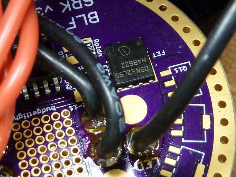
Quick answer to some of WTF’s questions is that we get large voltage spikes at the switching node and the + supply of the driver, inductive kickback when the FET switches off at every PWM pulse. As can be expected, the spikes are worse with higher current and longer LED wires (the wires are the main source of the inductance). Obvious solution for now is to add bypass capacitance on the feed to the driver, something we sacrificed somewhat to get more stable supply to the MCU. No reason not to have both on the bigger boards and apparently a requirement on hi-power 2S FET+1 builds.
Oh boy. Took some measurements last night with the 404 FET, then swapped to Hyperion, began measurements - then blew the 7135 once again . Weird - seemed to work for a decent amount of time on the 404. It's hard to figure. I think even after fixing C3, going into the config UI, it wasn't turning on the main LED's, but then i couldn't repeat that problem - config UI blinks worked after that.
I still got the modded firmware with the 7135/FET channels separated ON and OFF.
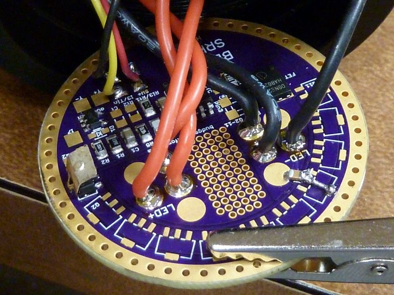
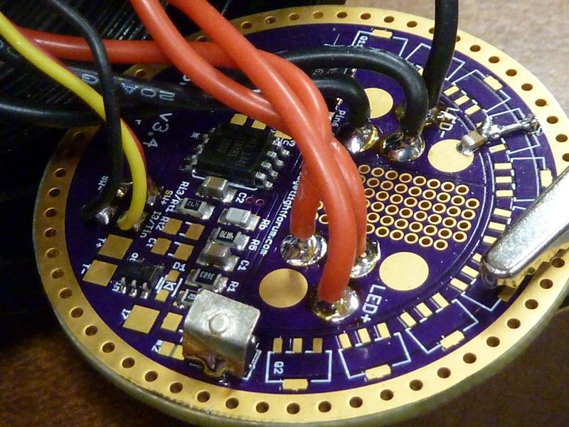
Ok, I replaced C1, C2, and C3 just in case. I moved C3 to where you suggested, and put back in the SIR404DP FET.
So now it's working like the current big 16X XHP50 S88 clone light works. Modes work fine, but the blinking done in configuration mode is flaky. I'm using a PWM value of 20 on the 7135. Thinking maybe I should use like a value of 3 on the FET for blinks, leaving the 7135 off. What do you think? I know it's a band-aid, but I really dunno what's going on, what the problem really is with the 7135. Maybe it will last forever like this, maybe fail in 5 minutes of use, dunno.
C2, C2, and C3 are all good 0805 10 uF caps. Didn't change C4 (0.1 uF).
Edit/Update:
Sorry bout all this DEL - it's weird with all these questions even though it's not your boar design. But I did update the firmware to have all blinks using only the FET, and it's working rock solid now. Also updated the ramping table for high output, so it shortens the 7135 levels. It's looking and working really well now. Benn playing with it.
I also raised the switch LED resistor to reduce the brightness, 4.7K to 6.8K and it's a nice improvement.
PWM 20 at 15.6 kHz gives 5 us pulses. The 7135 needs about 6 us to fully turn on, so we are right at the edge there. And C4 can interfere with all of this. C4 is recommended in some of the 7135 datasheets, but the 7135 was probably never intended to be PWMed. I would try removing C4 to see if the blinking behaves normally, hopefully C3 by itself will prevent frying the 7135.
Let me know how that 7135 holds up. I assume it is a new one and the only misbehavior up to now is the flaky blinking? Tomorrow is supposed to be rainy day here, may get some time to work on this.
I get that clicking strobe sound on all my high-powered FET lights. It opens the flood gates and then slams them closed so hard it makes an audible sound. I even hear it on my Emisar D4 with a half-empty 18350 cell. It’s amazing the tiny13 is able to withstand that without complaints or any attempt to shield it.
 .
.
 . Weird - seemed to work for a decent amount of time on the 404. It's hard to figure. I think even after fixing C3, going into the config UI, it wasn't turning on the main LED's, but then i couldn't repeat that problem - config UI blinks worked after that.